To really test the raw quality (so that's clarity, transparency, detail etc.) I often listen to a live recording of Anouk - "It Wasn't Me" (Live From Oosterpoort), a live recording of Eagles - "Hotel California" (Hell Freezes Over), Pepe Romero - "Farrucas", Stevie Ray Vaughan - "Tin Pan Alley", Tears For Fears - "Bad Man's Song" and I think The Handsome Family - Singing Bones is also a great album for sound quality. Many of the songs are also often played during demonstrations at Chattelin.
I really like a number of the songs above to listen to normally as well but normally I mostly listen to rock, alternative in particular. Like Pink Floyd, Supertramp, Genesis and obviously many more (my playlist is over 1500 songs). So to really test if the speakers are emotionally grabbing me, and to see what kind of punch they pack during loud playback of loud, complicated songs, I often play some of that, even though most of it isn't recorded too well, unfortunately.
Good job!
Though I almost exclusively listen to Classical, I am a great fan of Van der Graaf Generator...most recommended 😉 first listen to the music and then look when it was recorded 😱
Bet wihes,
M.
I've upgraded the crossovers on my Swan 3.1 speakers and in the process, replaced the 47uf electrolytic with a poly equivalent. Are there any concerns with the proximity of the large capacitor and the 2R resistor underneath? It's not touching and I don't think I can move the capacitor any further away.
The orientation and placement of the inductors is more concerning... I know there are experts here that can advice, or look for it on experts' sites.
Best wishes,
M.
The orientation and placement of the inductors is more concerning... I know there are experts here that can advice, or look for it on experts' sites.
Best wishes,
M.
The c-coils are far enough apart as to not cause any impact on inductance.
I've upgraded the crossovers on my Swan 3.1 speakers and in the process, replaced the 47uf electrolytic with a poly equivalent. Are there any concerns with the proximity of the large capacitor and the 2R resistor underneath? It's not touching and I don't think I can move the capacitor any further away.
Looks serious. I'm using both air core and ferrite core (small diameter ferrite rods) in Xovers these days. Using high frequency ferrite for bigger chokes allows you to use thicker wire and less turns. Lower resistance. I wind my own.
The c-coils are far enough apart as to not cause any impact on inductance.
Are you sure? 😕
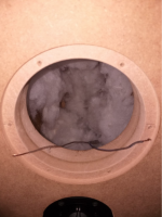
I positioned them properly, added damping material and set the filters and DSP. I have covered all walls of the woofer chambers with damping. I first also did this with the midrange chamber but I removed most of the material again in the end, only leaving the back walls covered to really make sure there's no echoes. With all walls covered the sound became overly bright, lost all of its snap and the SPL dropped with I think nearly 6 dB. It was just absorbing way to much of that magical Satori acoustics energy. My special design of midrange chamber is already doing a amazing job of diffusing the sound waves!
Now with the DSP properly set up, the speakers obviously sound even better, a lot. Man these speakers are just some of the best I've ever heard. Listening to Natalie Merchant - "The Peppery Man". It's as if those cowboys are hidden behind my speakers. And the snap and overal beauty of guitar chords have gotten even better!
Now with the DSP properly set up, the speakers obviously sound even better, a lot. Man these speakers are just some of the best I've ever heard. Listening to Natalie Merchant - "The Peppery Man". It's as if those cowboys are hidden behind my speakers. And the snap and overal beauty of guitar chords have gotten even better!
Attachments
-
 Schermafbeelding 2018-12-08 om 15.13.05.png467.5 KB · Views: 2,080
 -
 Schermafbeelding 2018-12-08 om 15.13.13.png559.9 KB · Views: 2,061
 -
 Schermafbeelding 2018-12-13 om 20.37.28.png931.1 KB · Views: 2,024
 -
 Schermafbeelding 2018-12-13 om 21.21.57.png779.6 KB · Views: 1,929
 -
 Schermafbeelding 2018-12-13 om 21.22.05.png628.5 KB · Views: 1,830
I’d concur with maxlornez’s concern as to proximity of the coils. Frankly, if you can find space to install a larger board, I’d be inclined to think about a rebuild. If not already familiar with his work, take a look at Troel Gravesen’s site. His rebuilds/ upgrades of classic multi ways should be considered a tutorial on parts layouts. I’d certainly entertain a more secure mounting of that large film cap, and any power resistors should be given as much breathing room as practical.
DIY-Loudspeakers
DIY-Loudspeakers
Willing to share a little more detail? The pictures show the sloped top, but I'm not sure what you did elsewhere.My special design of midrange chamber is already doing a amazing job of diffusing the sound waves!
Also did you open the rear of the baffle so the mid can breathe? If not, see this.
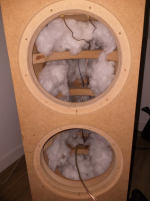
The sloped top has nothing to do with it. Well, maybe it has a miniscule effect on diffraction but it's purely cosmetic. I made the midrange chamber round with 25 mm plates with smaller getting holes in them. Instead of rounding their edges the full 25 mm and make the edges of the different plates anlign perfectly, I left some ridges so the sound waves will numb into them and break up, instead of traveling amongst the smooth walls and coming back to the driver.
Attachments
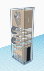

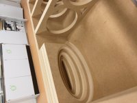
Those stacks of solid MDF also make the structure extremely stiff. Tweeter is also housed in a hole in that solid piece so it's in its own completely sealed extremely stiff/hard/solid chamber.
I still found the measurements to be unrealistic in the lower region below 30 Hz so instead of a 0 - 20 kHz sweep measurement I went to use the SPL meter and the tone generator. And boy, these woofers are in for some serious depth. Calibrating the level to 75 dB with pink noise. I found out it is a smooth rising response to 77 dB @ 30 27 Hz, this is because of the slight intended bass boost because I like a little bit extra thump. Then going lower, in my room these puppies are pushing an F3 of 21 Hz! with still reasonable output in the 15s!
stacks of solid MDF also make the structure extremely stiff
It would be stiffer yet if you’d used quality plywood. Nice job otherwise.
dave
I positioned them properly, added damping material and set the filters and DSP. I have covered all walls of the woofer chambers with damping. I first also did this with the midrange chamber but I removed most of the material again in the end, only leaving the back walls covered to really make sure there's no echoes. With all walls covered the sound became overly bright, lost all of its snap and the SPL dropped with I think nearly 6 dB. It was just absorbing way to much of that magical Satori acoustics energy. My special design of midrange chamber is already doing a amazing job of diffusing the sound waves!
Now with the DSP properly set up, the speakers obviously sound even better, a lot. Man these speakers are just some of the best I've ever heard. Listening to Natalie Merchant - "The Peppery Man". It's as if those cowboys are hidden behind my speakers. And the snap and overal beauty of guitar chords have gotten even better!
I'm assuming that the first graph is what your system sounds like without the dsp alterations. If you do decide to rebuild your passive crossovers I would create a little bit of a bbc dip in the 800-2000 hz range as it looks like baffle diffraction is playing a part in the mid range frequency area. I would also chamfer the front baffle as it looks like you've gone to a lot of work to build good cabinets and this helps when playing louder and also off axis listening.
Thanks for the extra info. Interesting approach!I made the midrange chamber round with 25 mm plates with smaller getting holes in them.
It's a fully active system so I can easily make changes to the crossovers but I don't think a dip in the midrange is necessary because I really like the way it sounds right now and don't think I'll want to change it. And I don't like equalizing the sound to make it seem sound nicer. Just give me the pure flat sound. If then doesn't sound nice, I'll rather look at making changes to the cabinet or drivers.
I was actually planning on making the baffle rounded and actually had it in my design because I think it looks nice and mainly of course for diffraction but the CNC machine I had acces to isn't able to make 3D movements. You need a 5-axle machine to do that and those are unfortunately pretty hard to come by. Luckily my parents are in the interior business and have a lot of contacts with woodworkers and furniture builders so maybe I will some day get to properly rebuild the cabinets.
By the way. What do you guys think of semi-venting the midrange? Just some small holes to let the midrange breathe just a little bit to avoid compression. Not that my midrange doesn't sound nice, AT ALL, but I see some companies like Wilson Audio, and I do think I can hear the midrange slightly changing at higher volumes in a bad way. It's not that worse at all but I just think I can hear a little left potential. Though, at over 15 L my midrange chambers already are rather huge for a 118 cm^2 Sd midrange which should really limit compression. Do you think compression already is pretty much impossible?
It's a fully active system so I can easily make changes to the crossovers but I don't think a dip in the midrange is necessary because I really like the way it sounds right now and don't think I'll want to change it. And I don't like equalizing the sound to make it seem sound nicer. Just give me the pure flat sound. If then doesn't sound nice, I'll rather look at making changes to the cabinet or drivers.
I was actually planning on making the baffle rounded and actually had it in my design because I think it looks nice and mainly of course for diffraction but the CNC machine I had acces to isn't able to make 3D movements. You need a 5-axle machine to do that and those are unfortunately pretty hard to come by. Luckily my parents are in the interior business and have a lot of contacts with woodworkers and furniture builders so maybe I will some day get to properly rebuild the cabinets.
By the way. What do you guys think of semi-venting the midrange? Just some small holes to let the midrange breathe just a little bit to avoid compression. Not that my midrange doesn't sound nice, AT ALL, but I see some companies like Wilson Audio, and I do think I can hear the midrange slightly changing at higher volumes in a bad way. It's not that worse at all but I just think I can hear a little left potential. Though, at over 15 L my midrange chambers already are rather huge for a 118 cm^2 Sd midrange which should really limit compression. Do you think compression already is pretty much impossible?
There is a db dropoff with an entirely closed cabinet. I've heard about 3 db so you have to account for it in your design. For me I would think that the midrange is less affected than if you we're running a two way and the cone was being pushed to distortion limit on the low end frequency. Maybe some others have some experience there. By the way are your woofers run in parallel or series. Is there an advantage to having two woofers in series or are you doing something different with your active crossovers and multi-amp setup.
I'm running two 8 ohm woofers in parallel because I think 4 ohm is a nice nominal resistance for a active system where there's no difficulties with a passive network and because the 8 ohm versions of this woofers performed slightly better in simulation because of the higher force factor. The differences were ever so slightly but it's the small things that matter.
Last edited:
A modest 2-way system with SBA SB16PFC25-4 and Seas 27TBFC/G.
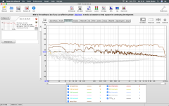
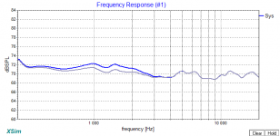
At first step only manufacturer's datasheet and simulation data were used, just out of curiosity how far the actual effects from the simulations would be. The result (for this particular design) is that the simulations are in the +- 2dB path with relation to the measurements, with the exception of the 60-80Hz and 2-2.4kHz regions where the error is a bit higher.
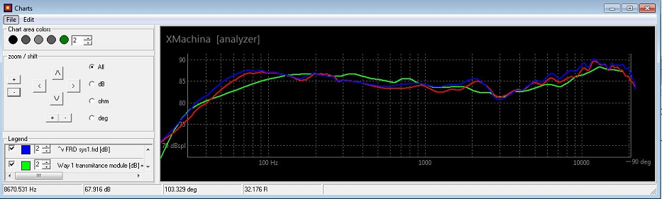
Green: characteristics determined from simulations (target). Blue and red: measured characteristics of L and R speakers.
(more about the first step of the design)
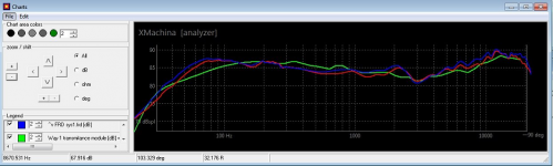
In the second step the system crossover was designed based on measurements. The target response was changed to be linear rather than contour-like.
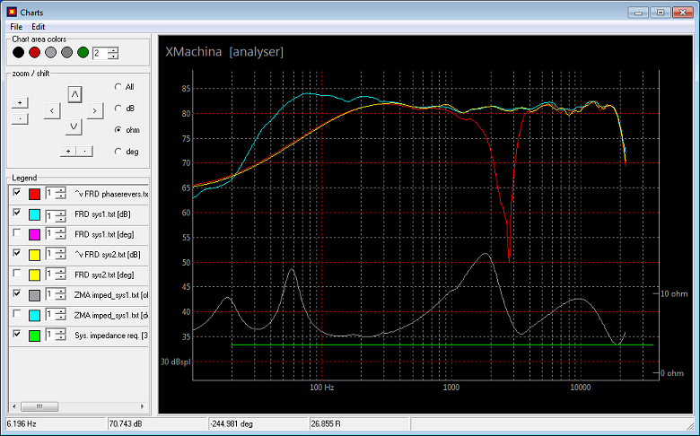
Frequency characteristics:
cyan: dBspl with nearfield LF measurements included,
green: dBspl for the second speaker (low frequency measurements are not included)
red: dBspl for the second set, reversed polarity,
gray: impedance module (with 4R horizontal line marker).
(more about the second step of the design)
At first step only manufacturer's datasheet and simulation data were used, just out of curiosity how far the actual effects from the simulations would be. The result (for this particular design) is that the simulations are in the +- 2dB path with relation to the measurements, with the exception of the 60-80Hz and 2-2.4kHz regions where the error is a bit higher.
Green: characteristics determined from simulations (target). Blue and red: measured characteristics of L and R speakers.
(more about the first step of the design)
In the second step the system crossover was designed based on measurements. The target response was changed to be linear rather than contour-like.
Frequency characteristics:
cyan: dBspl with nearfield LF measurements included,
green: dBspl for the second speaker (low frequency measurements are not included)
red: dBspl for the second set, reversed polarity,
gray: impedance module (with 4R horizontal line marker).
(more about the second step of the design)
Attachments

Likely not the right place for a build thread, nor for constructive criticism, but the 43 ohm resistor across the woofer is likely going to get HOT as it will see the entire bass range. If you honestly have to have this part for some reason, make it 25W+ rated.
Normally, this would be to likely to droop the Fs magnitude of the woofer to bring down the ripple that the LP coil would induce from this. It still is not the best idea for a fix in this regard. My opinion if you have to have it, is to keep the value above 50 ohms. You don't want a lot of current going through it, and the value is better above this point.
Later,
Wolf
I'm sorry that I possibly posted in the wrong thread. If this is the case, could someone help please and redirect this to more appropriate place...Likely not the right place for a build thread, nor for constructive criticism
Power handling of the 43ohm resistor was also my concern so I did the following estimation:but the 43 ohm resistor across the woofer is likely going to get HOT as it will see the entire bass range. If you honestly have to have this part for some reason, make it 25W+ rated.
Normally, this would be to likely to droop the Fs magnitude of the woofer to bring down the ripple that the LP coil would induce from this. It still is not the best idea for a fix in this regard. My opinion if you have to have it, is to keep the value above 50 ohms. You don't want a lot of current going through it, and the value is better above this point.
Later,
Wolf
For the 4ohm midwoofer applied power handling is given as P=40W so the max RMS voltage can be estimated
P=(U^2)/r => U=(P*r)^.5=(40*4)^.5=12.6Vrms (17.8V sine amplitude). Exceeding this for a longer time would probably damage the speaker.
This voltage was used for estimation of max power dispatched in the 43ohm resistor (assuming worst case frequency for which coils make short circuit and capacitors are circuit breaks), P=(12.6^2)/43= 3.7W so the conclusion was that there should be no problem as even the cheapest 5W resistor still has some power headroom (actually I applied 10W resistor for this one).
Simple experimental verification. The system was played with average signal levels (volume control at 10-11 o'clock position) for approx 2 hours then resistor temperature was measured with a simple procedure (touching finger). I wasn't hot at all in fact it didn't even feel warm.
Why is this resistor used - it makes a significant correction in the mid range, see graph. Blue:resistor removed from the circuit, Gray: resistor used.
Attachments
- Home
- Loudspeakers
- Multi-Way
- System Pictures & Description