Sorry for keeping you waiting, guys 😉. I haven't been able to do much lately. But last sunday I got to work on the second proto again 🙂. So here's another photoshoot...


It barely fits 😀
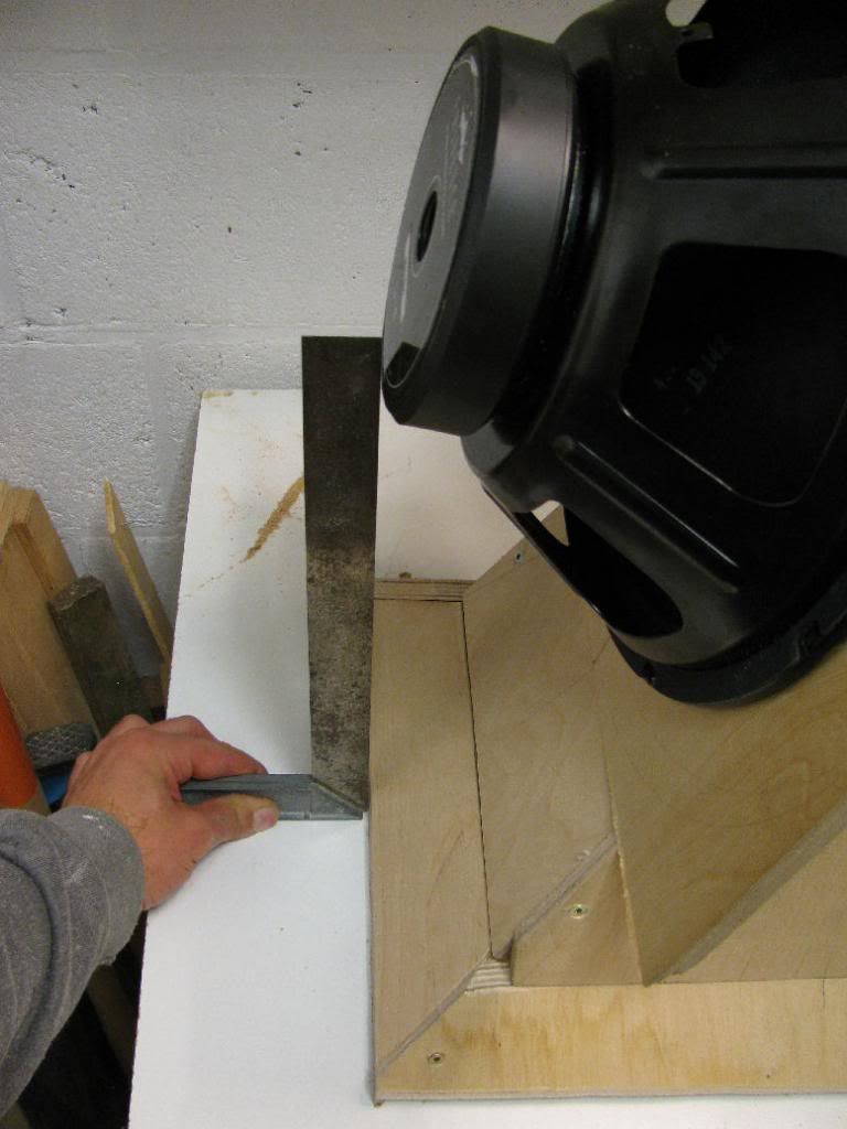
Sadly the other side is going to give me some trouble 😡
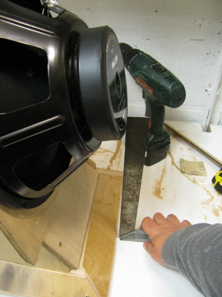
Not quite perfect, but urethane construction glue will fill up those holes nicely 🙄.

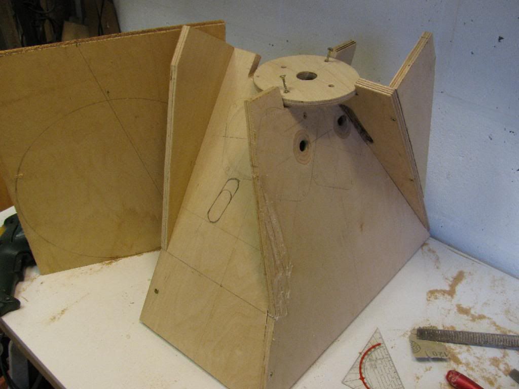
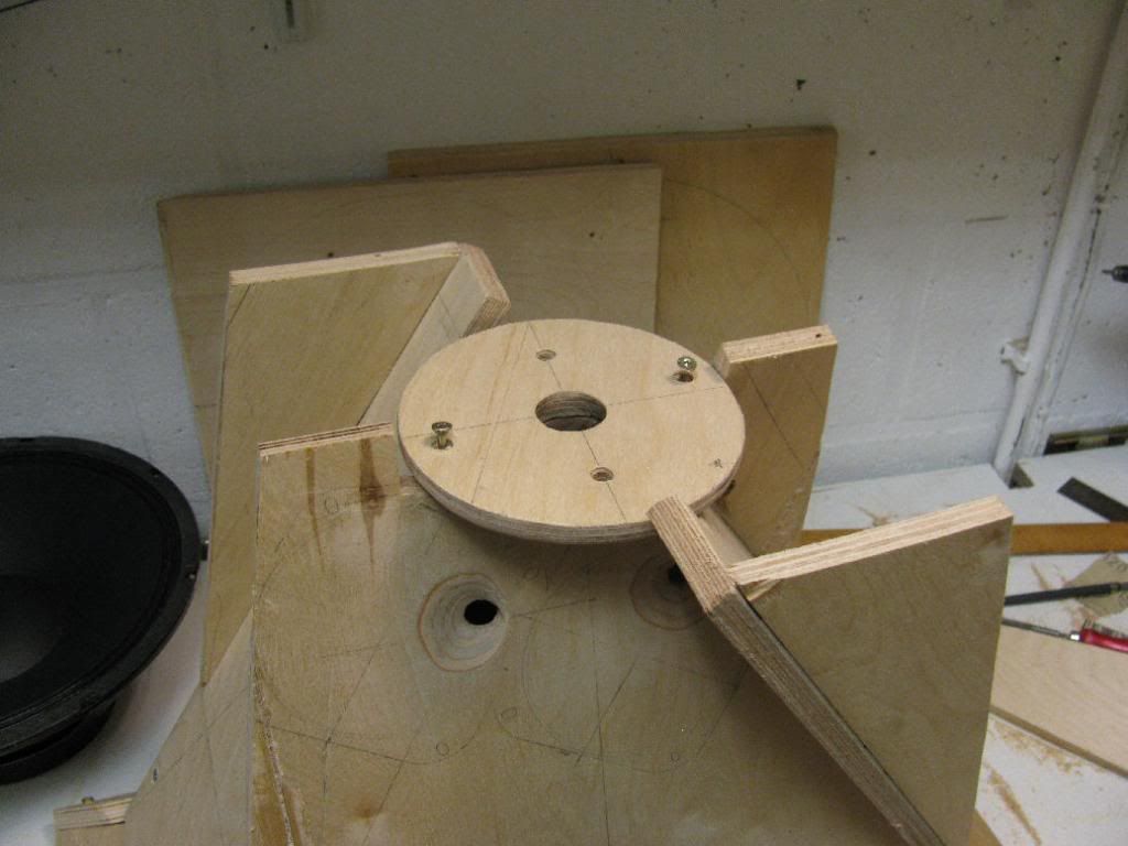
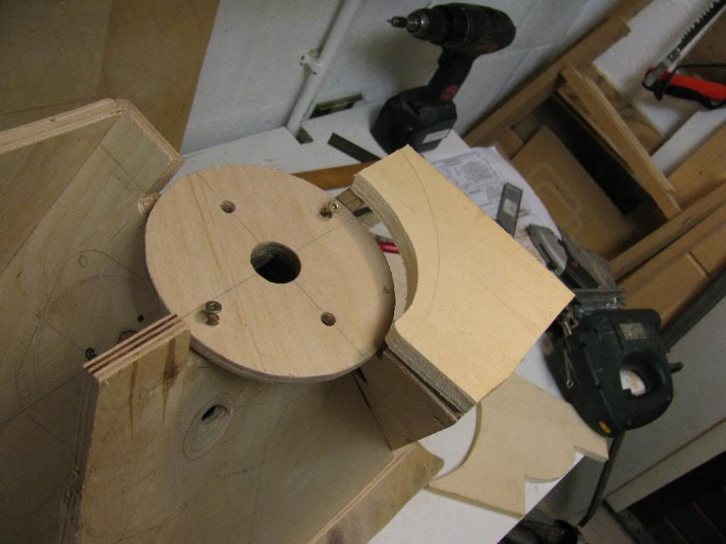
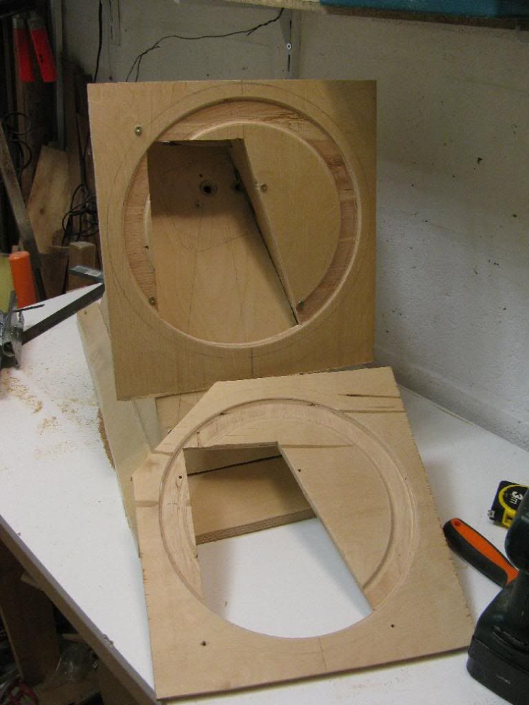
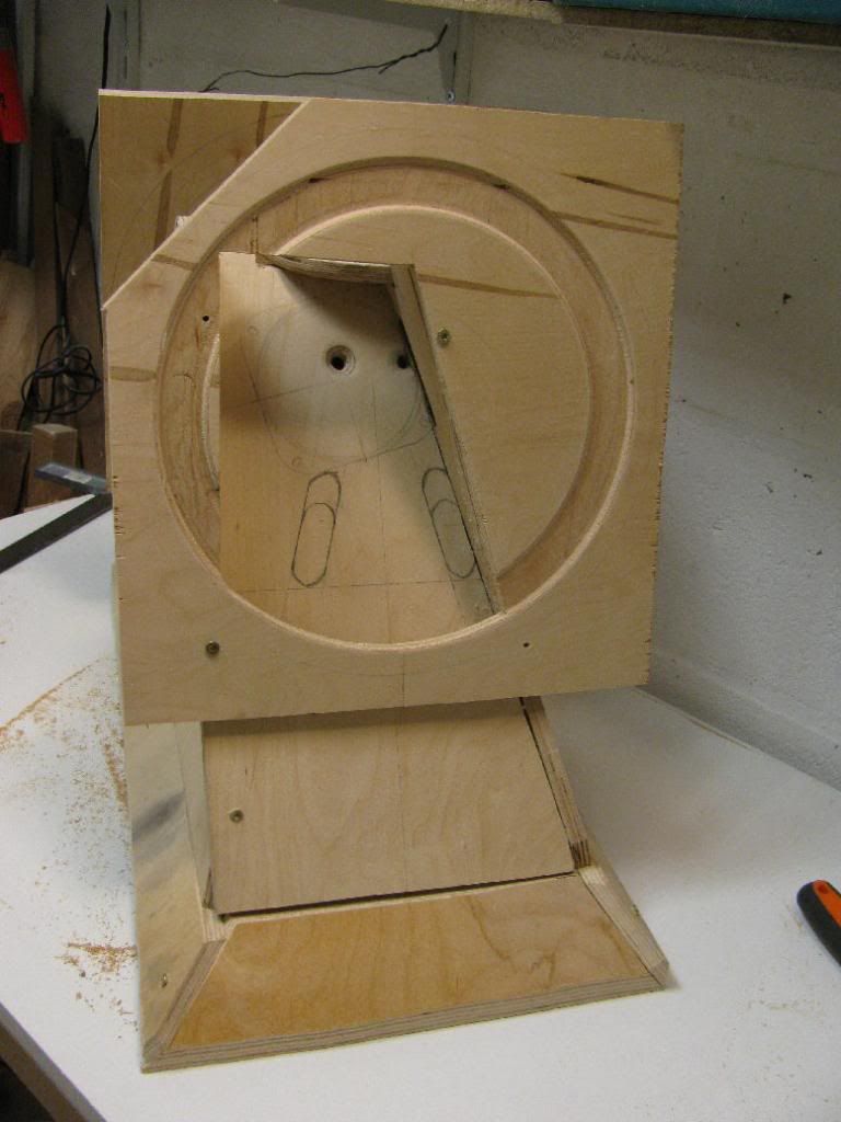
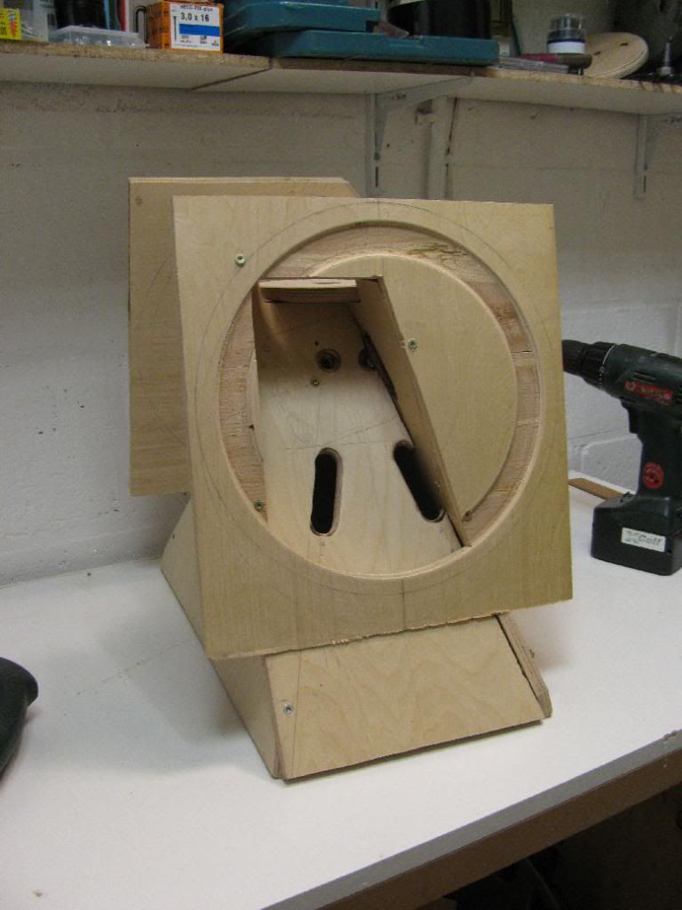
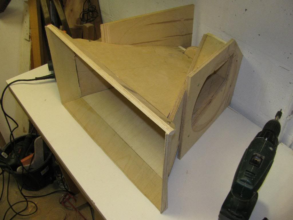
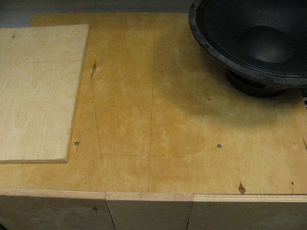
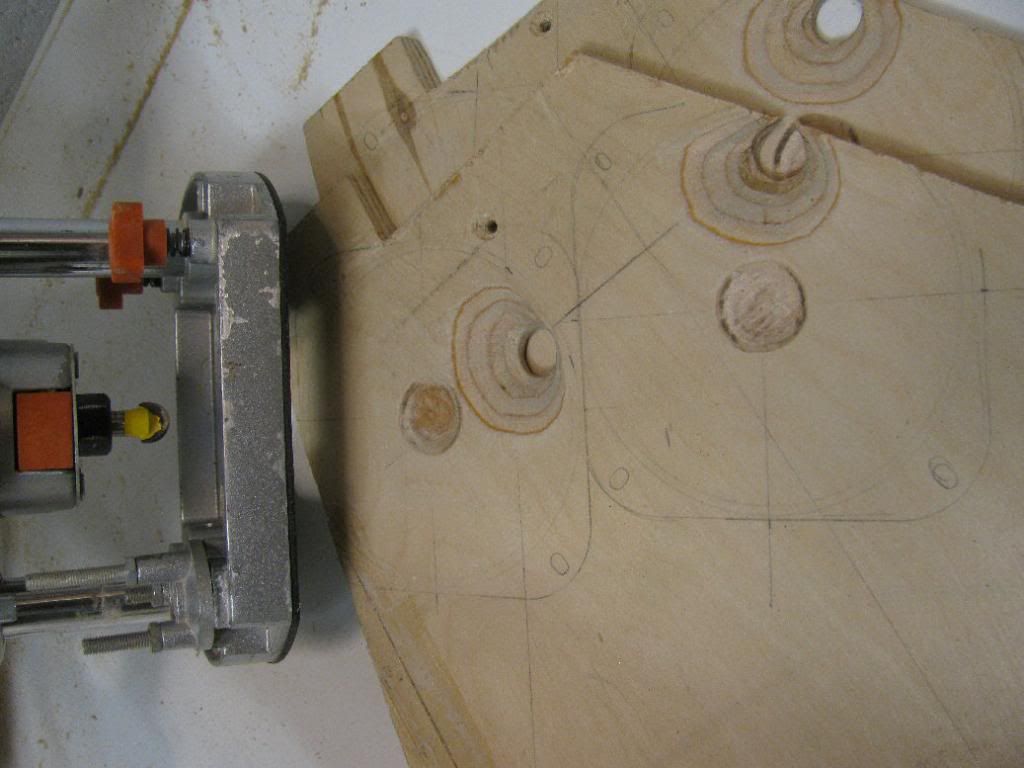
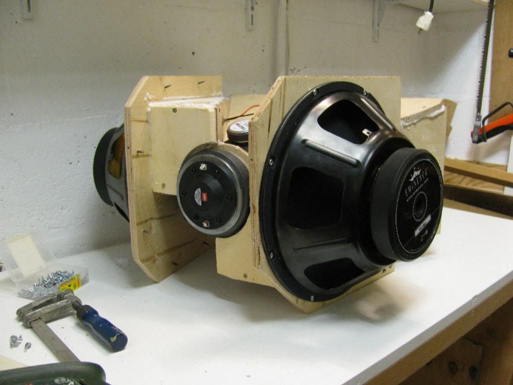
Now for the woofer baffles. Let's cut this part away...
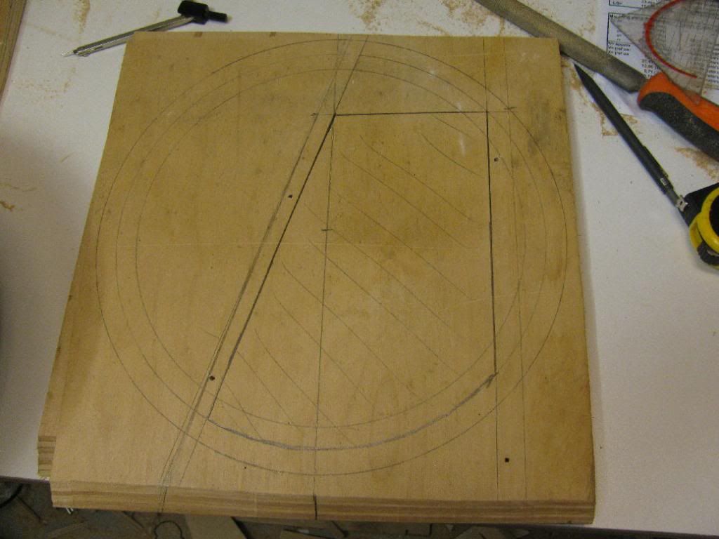
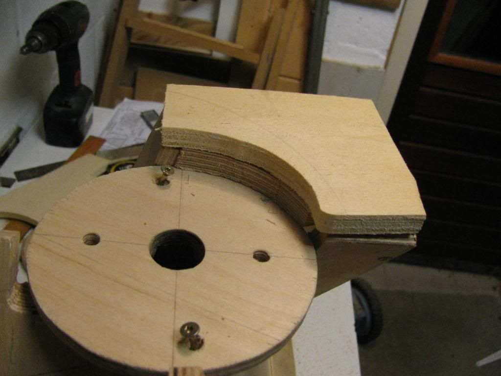
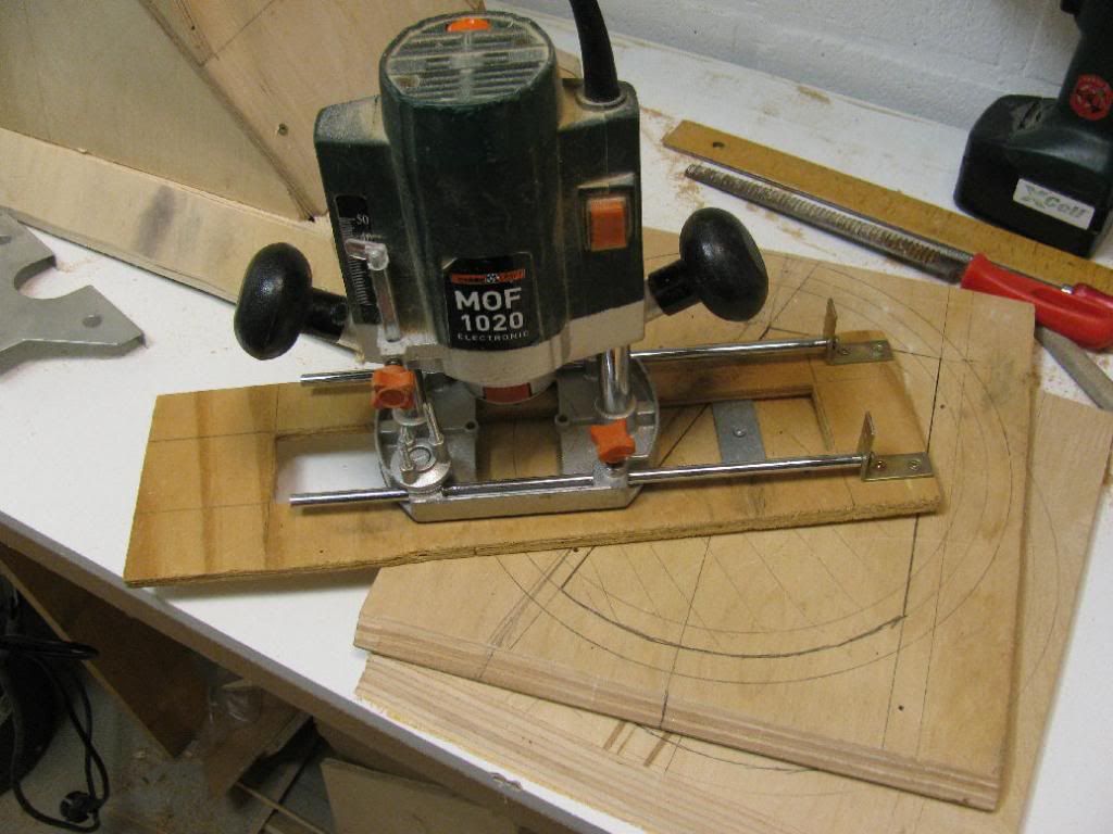
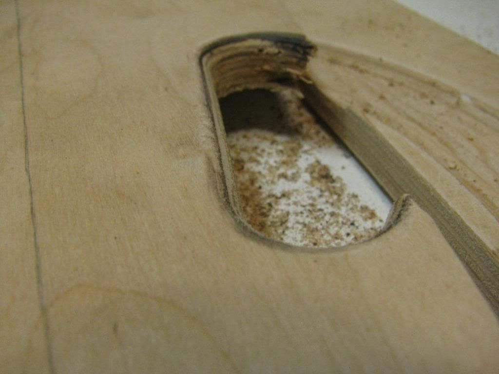
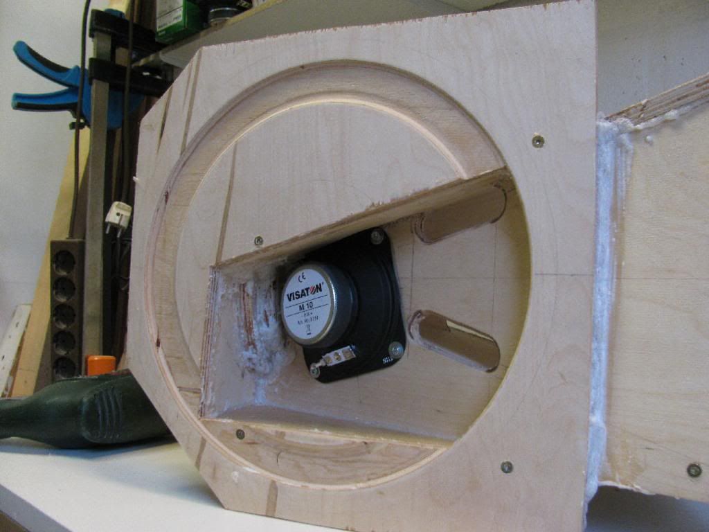
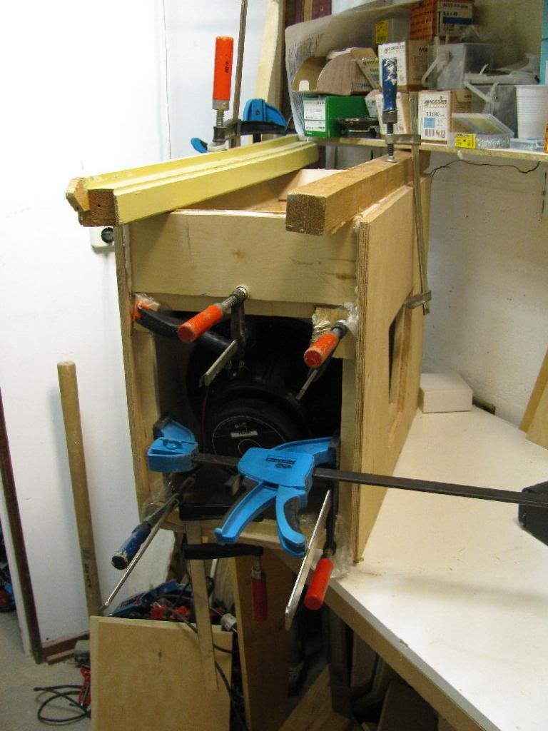
But first, router out a nice circle to prevent cone slap using my self made circle jig 😎.
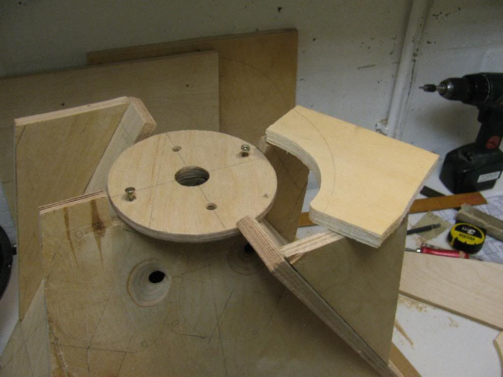
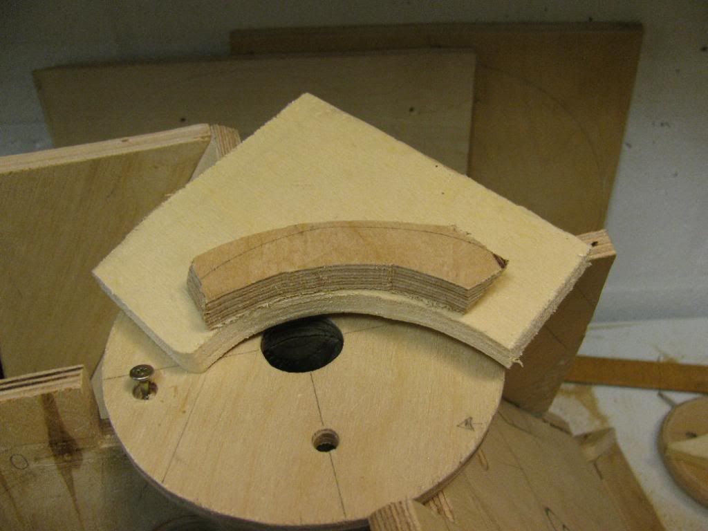
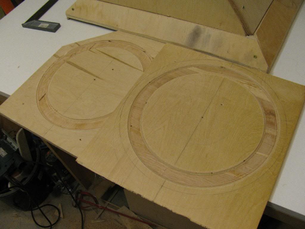
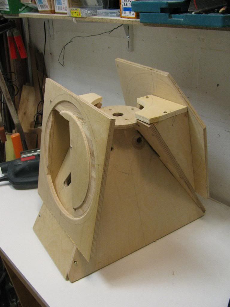
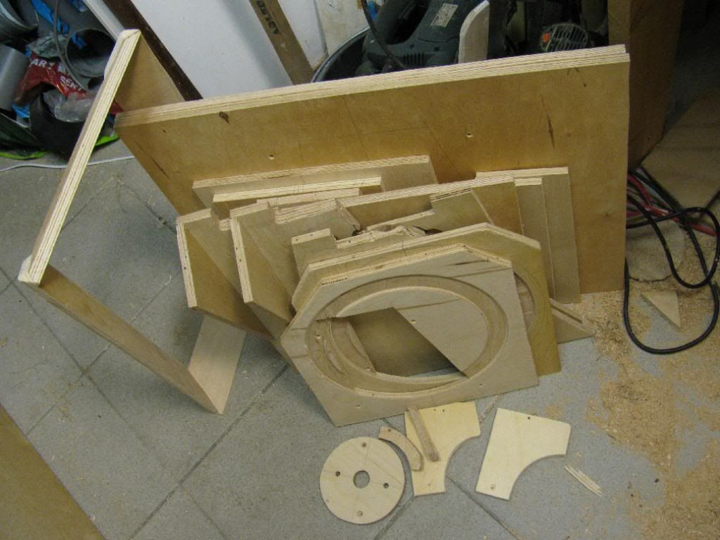
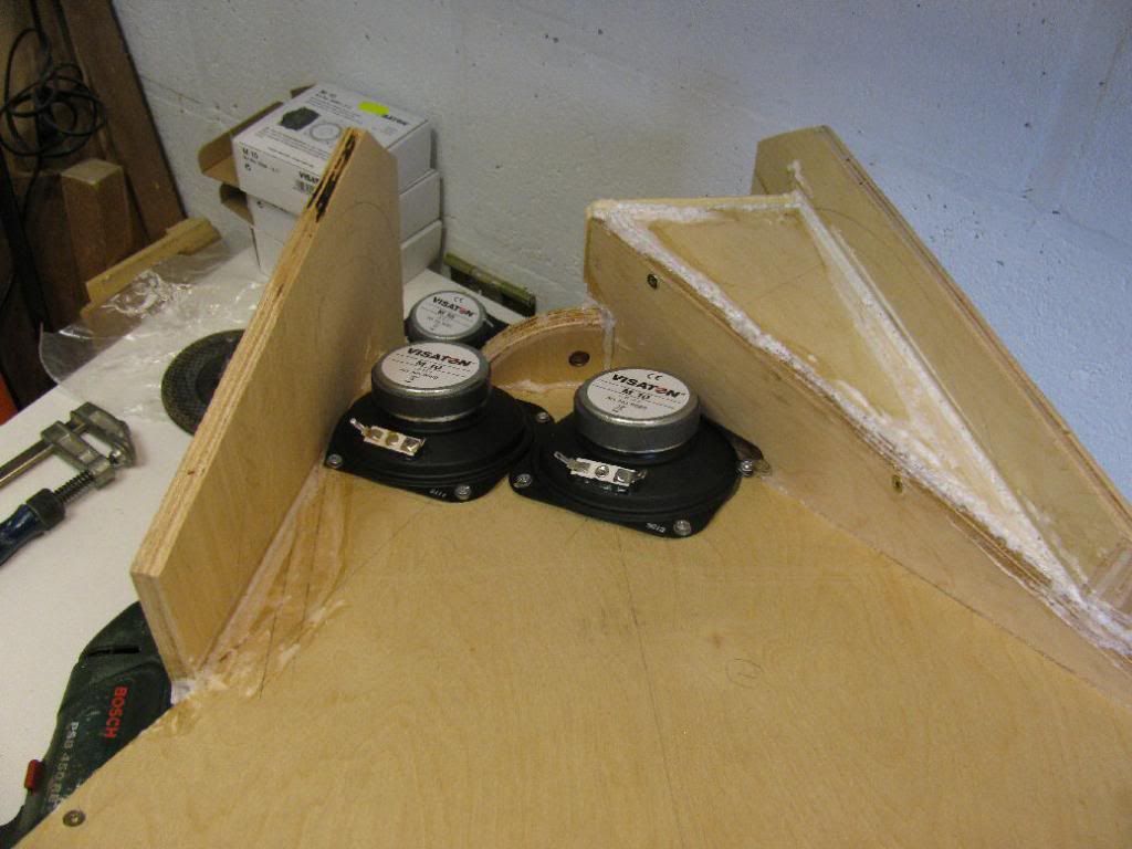
No, wait, let's do that on the other side, 'cause this side is supposed to be on the inside. Too late 😡. Ok, so I ****** up. Lets make another baffle... (the one with the missing corner is the new one. Why is the corner missing, you ask? It's just because I had this piece laying around I I couldn't see it hurting the functionality. I might even cut corners on the other baffle as well and loose a little weight 😉 ).
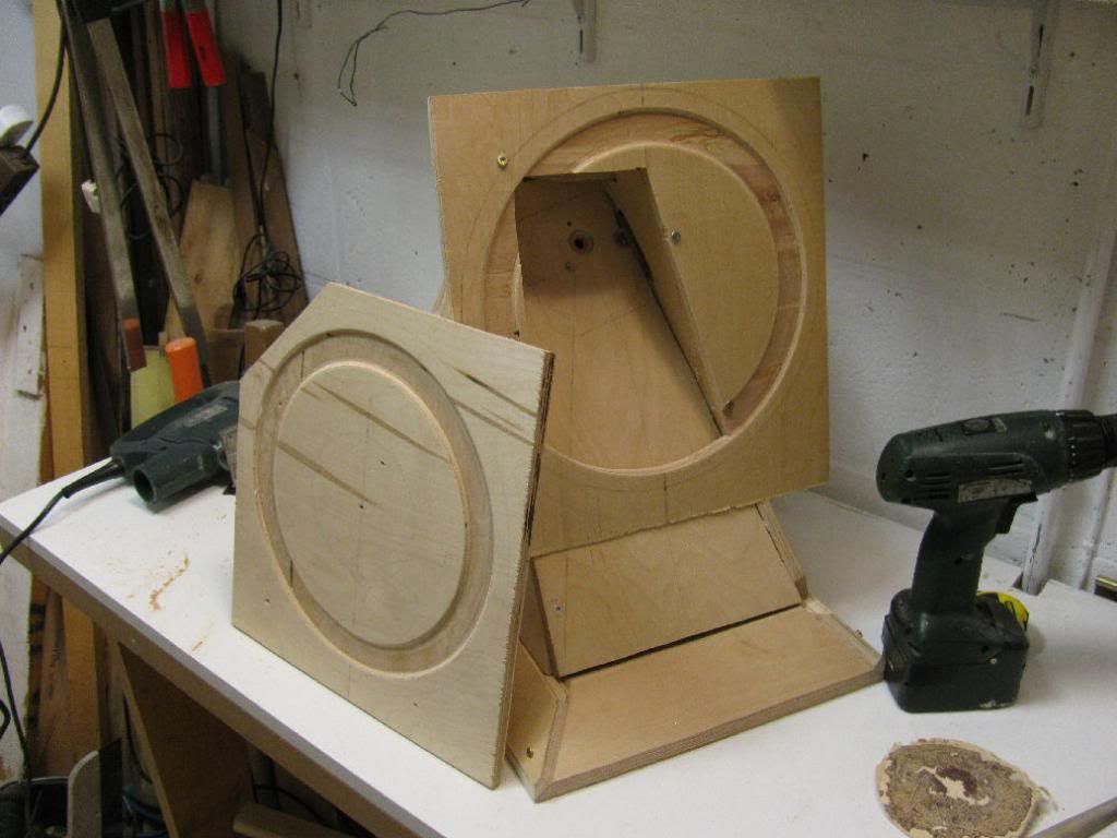
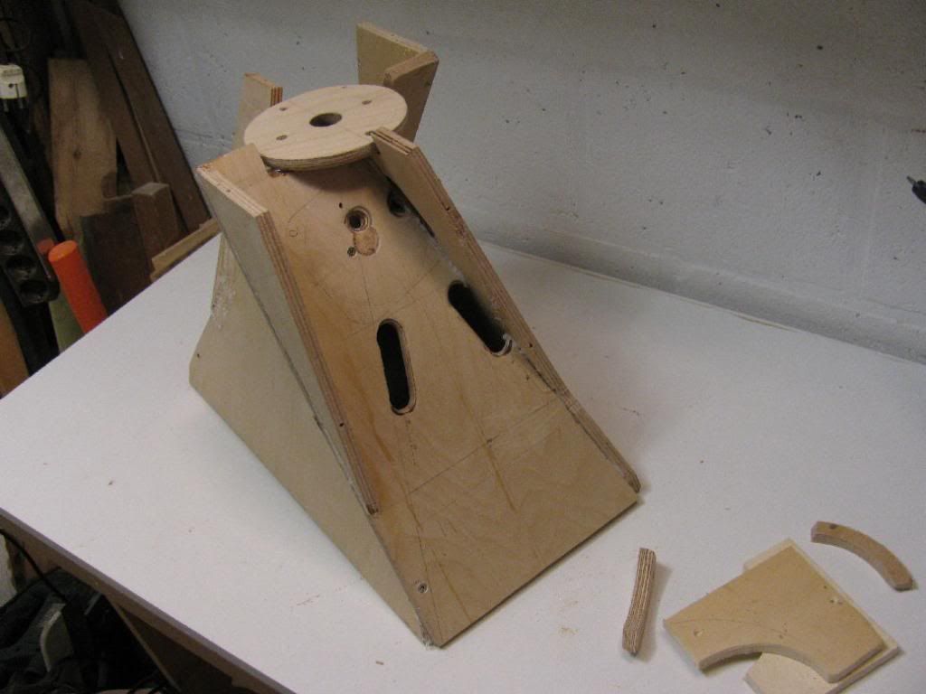
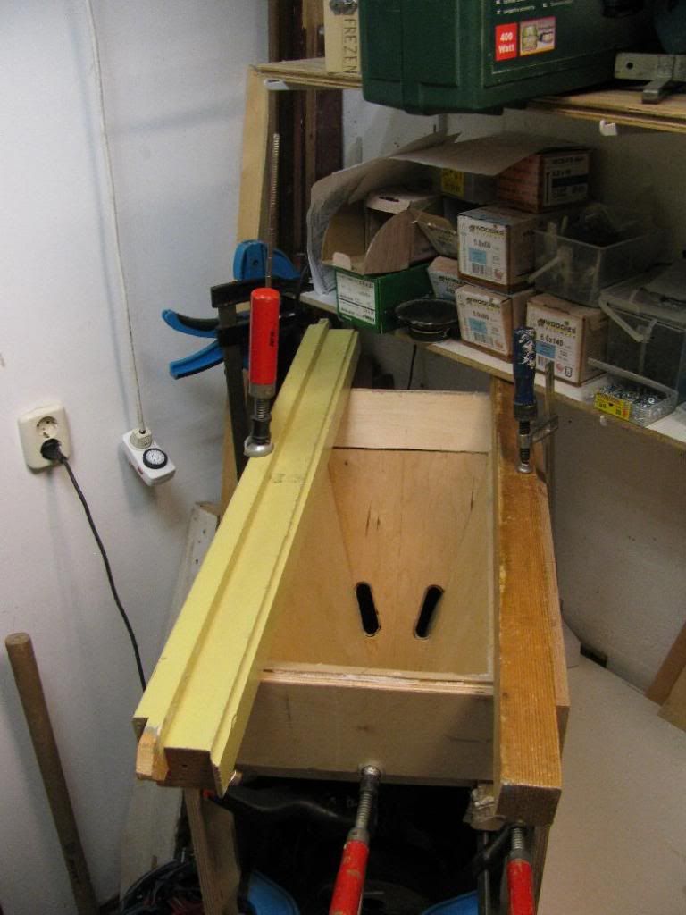
Yeah, it's not symmetrical, but I don't think that's going to matter. Simulations predict I could use the larger volume of the front chamber.
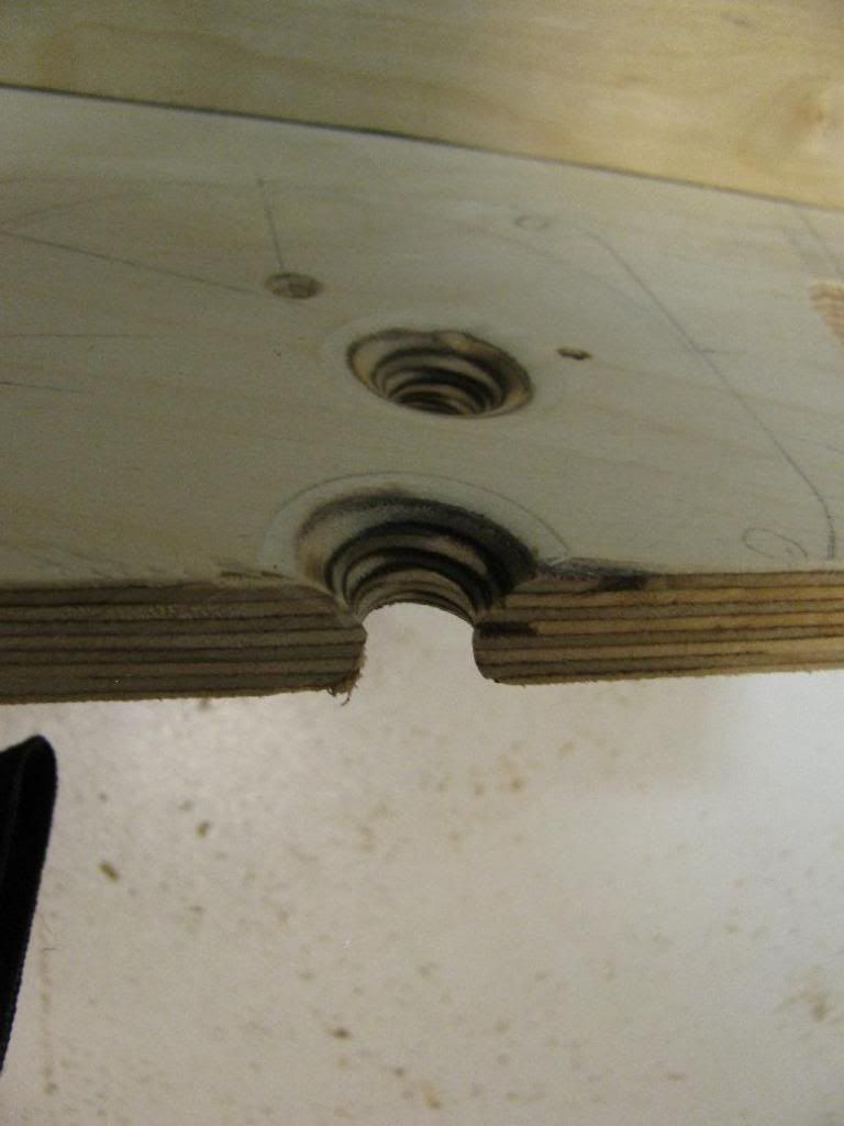
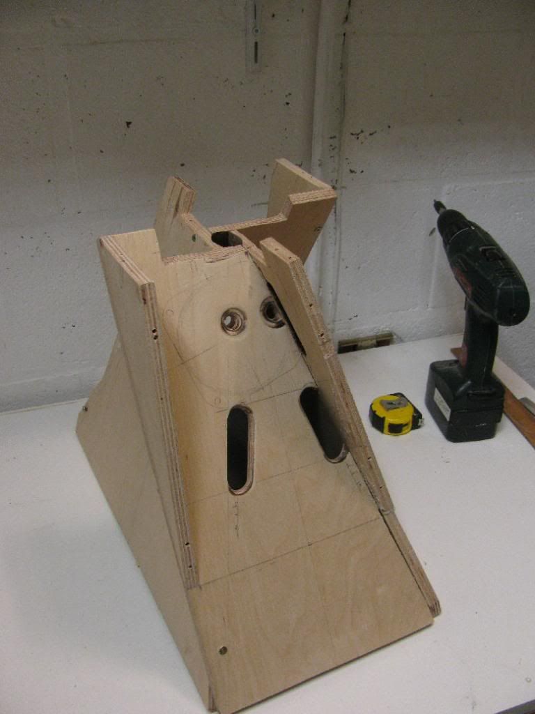
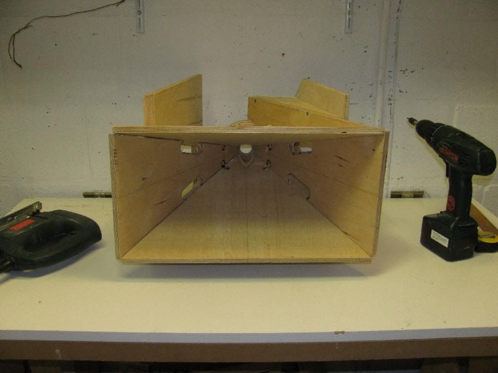
Woofer ports are 20mm wide, 70mm long.
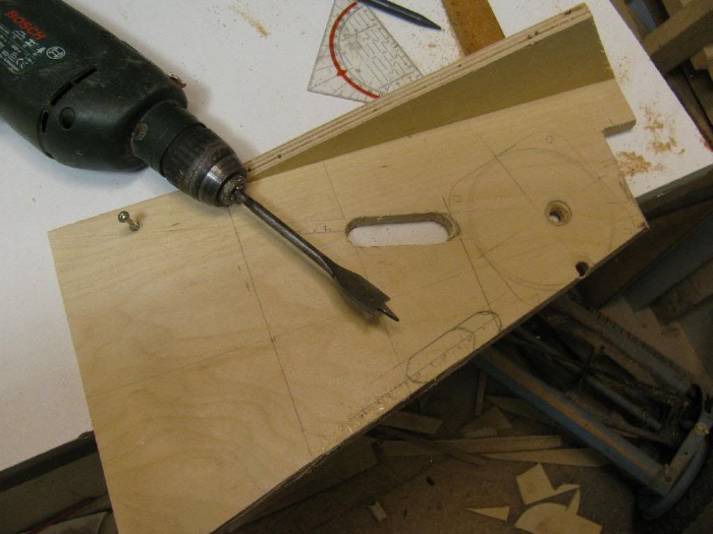
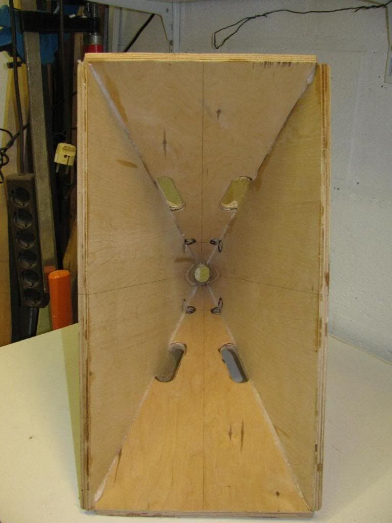
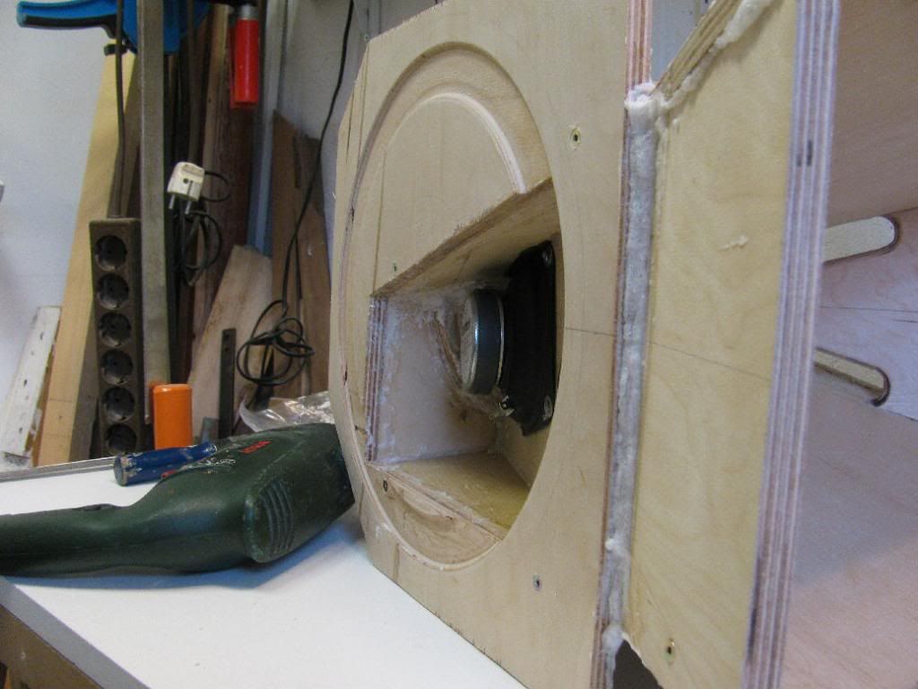
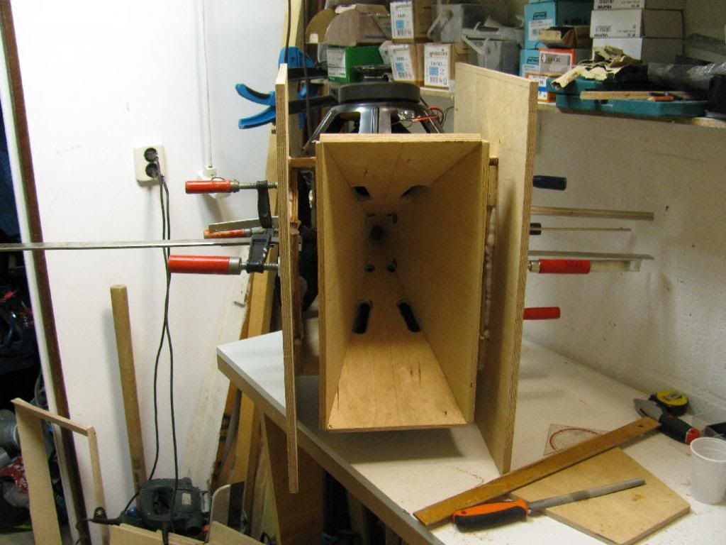
Mid ports rounded while I had the horn sides off.
Curve on the horn side is shorter than underneath the mid driver.
Woofer ports rounded.

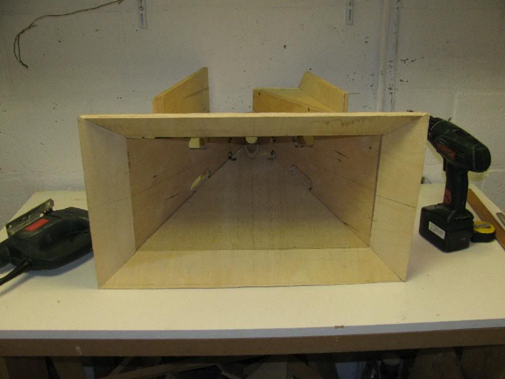
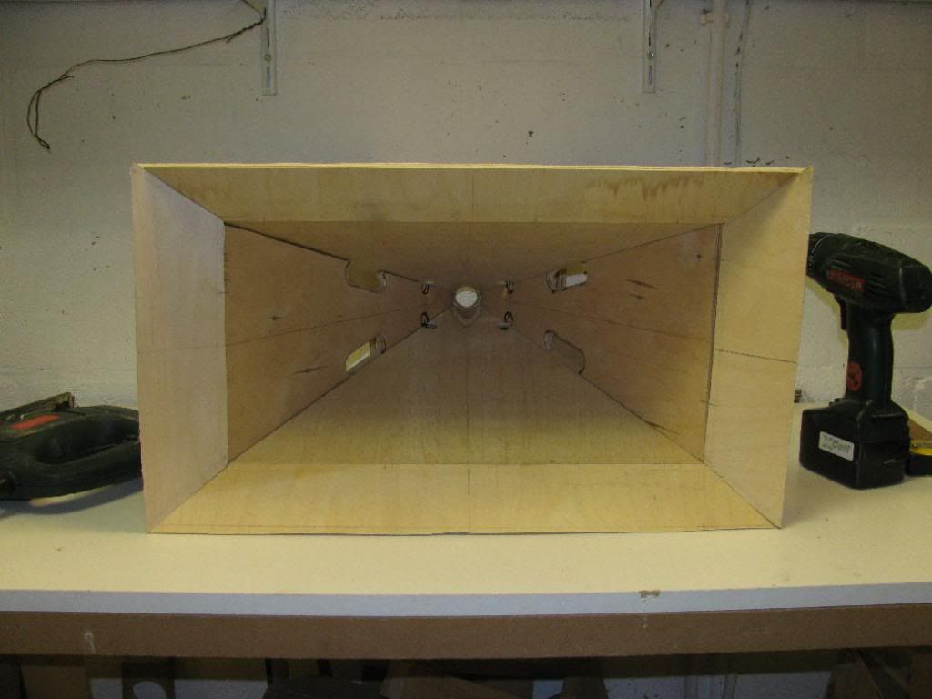
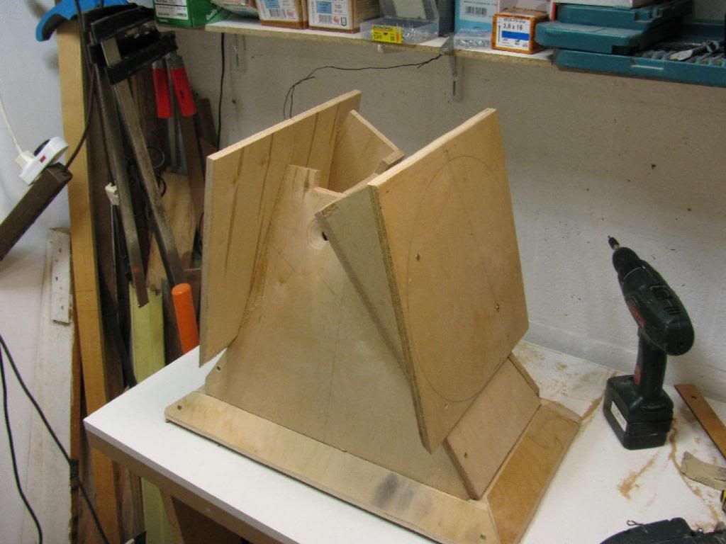
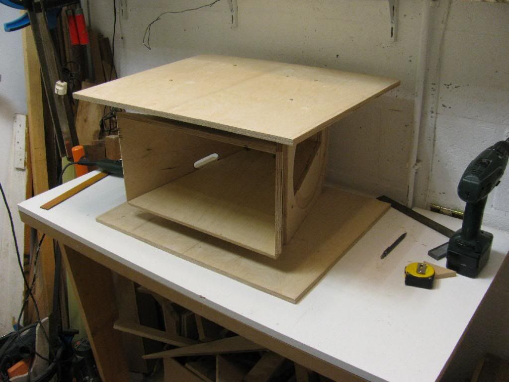
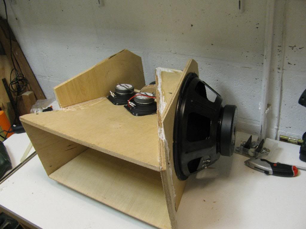
That's all for now. Before I glue it all together, I guess it's best to construct the outer hull (or box) to see if I can get it all to fit.


It barely fits 😀

Sadly the other side is going to give me some trouble 😡


Not quite perfect, but urethane construction glue will fill up those holes nicely 🙄.


Now for the woofer baffles. Let's cut this part away...

But first, router out a nice circle to prevent cone slap using my self made circle jig 😎.

No, wait, let's do that on the other side, 'cause this side is supposed to be on the inside. Too late 😡. Ok, so I ****** up. Lets make another baffle... (the one with the missing corner is the new one. Why is the corner missing, you ask? It's just because I had this piece laying around I I couldn't see it hurting the functionality. I might even cut corners on the other baffle as well and loose a little weight 😉 ).


Yeah, it's not symmetrical, but I don't think that's going to matter. Simulations predict I could use the larger volume of the front chamber.


Woofer ports are 20mm wide, 70mm long.

Mid ports rounded while I had the horn sides off.

Curve on the horn side is shorter than underneath the mid driver.

Woofer ports rounded.


That's all for now. Before I glue it all together, I guess it's best to construct the outer hull (or box) to see if I can get it all to fit.
Construction continues 😀...
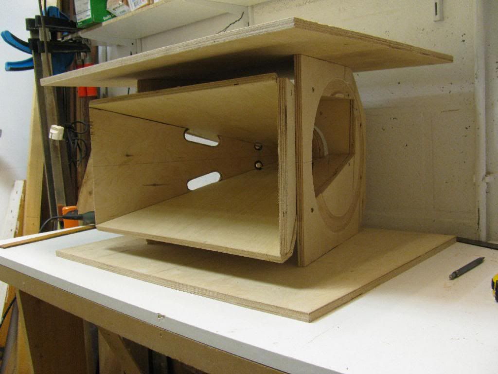

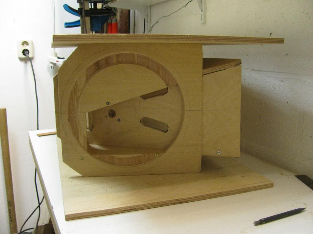
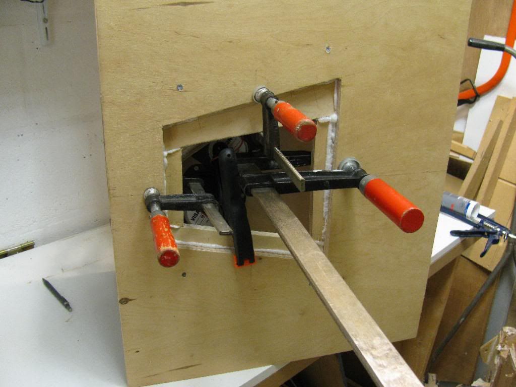
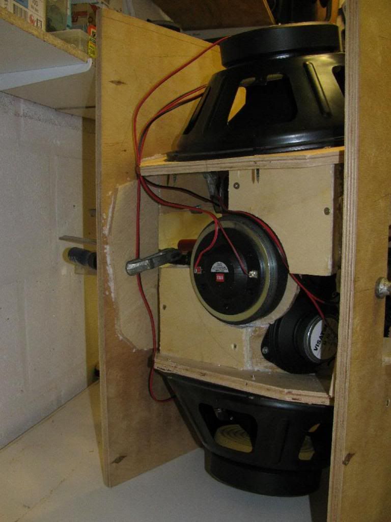
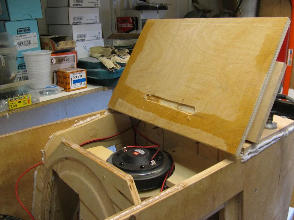
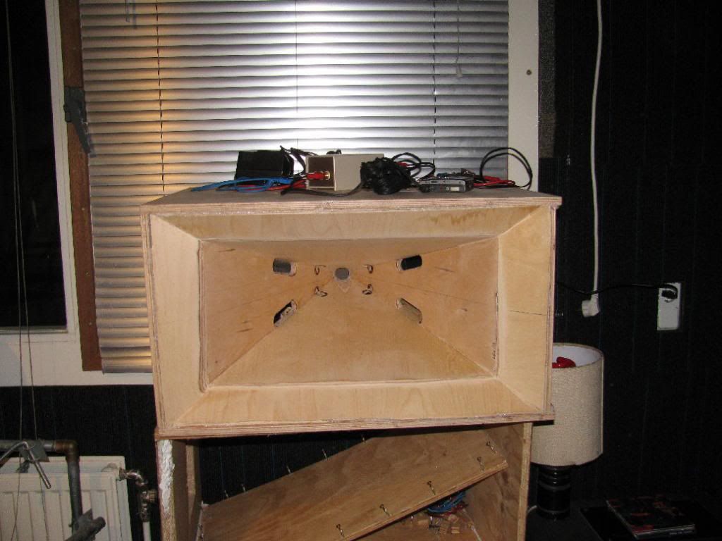
Woofer access:
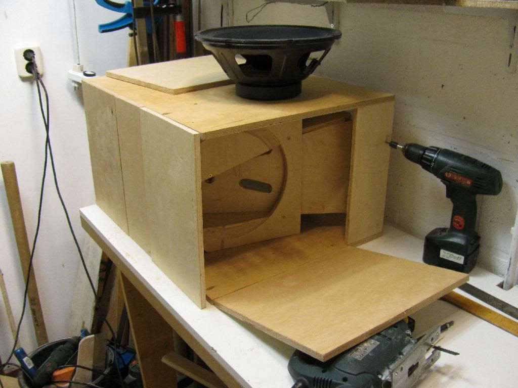
Compression driver access:
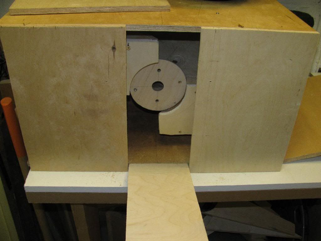
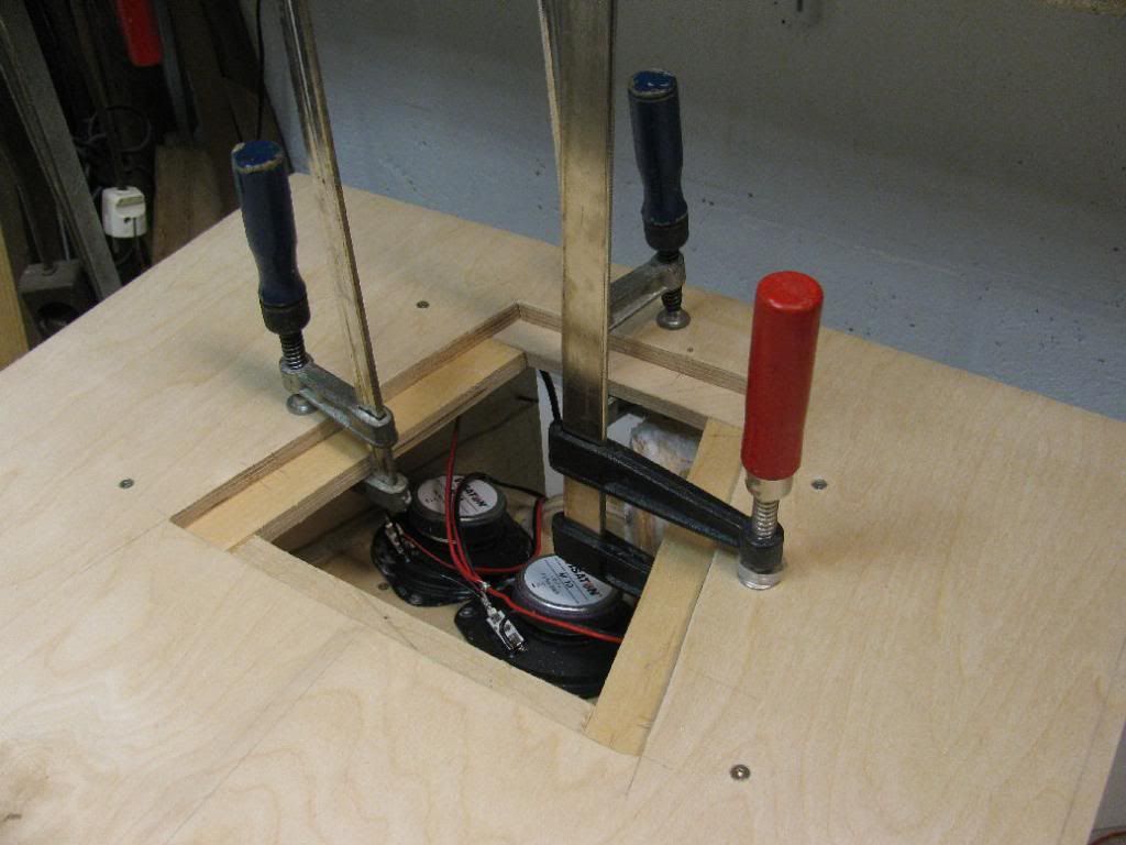
Hatch for access to the top and bottom mids -under construction- :
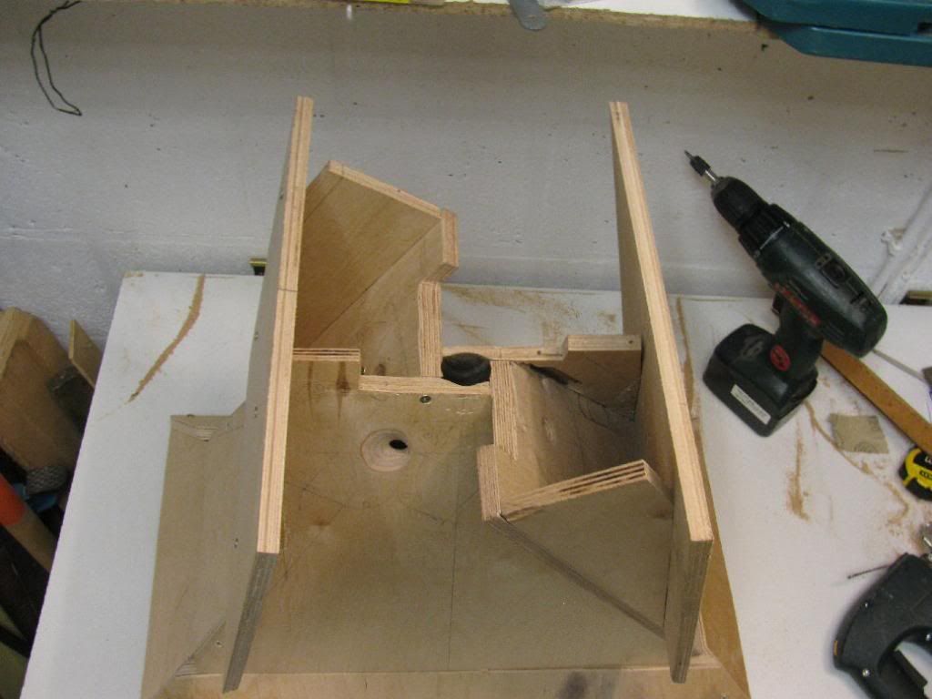
This is all the wood that goes in.
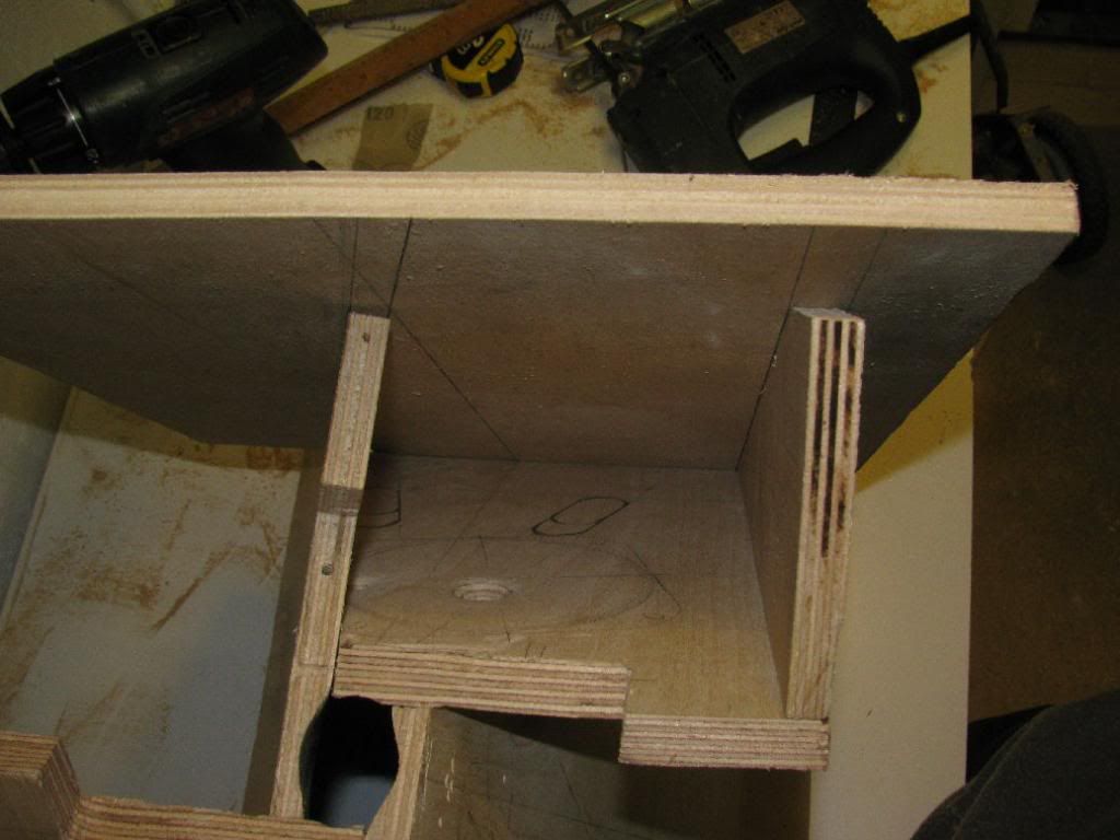
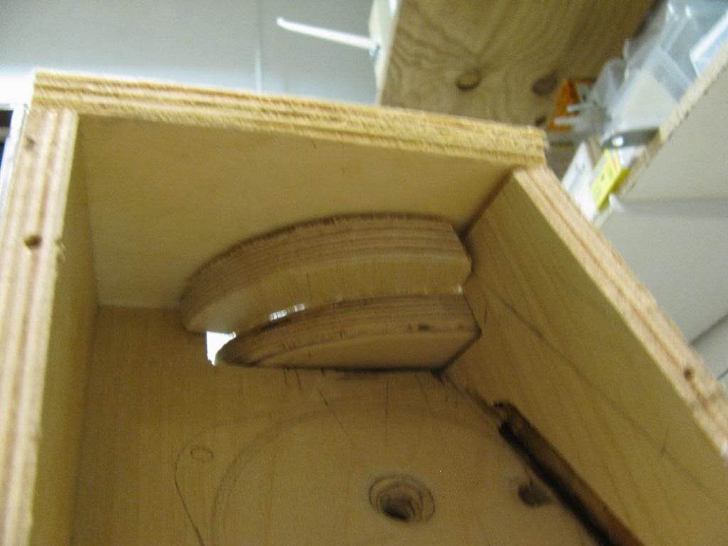
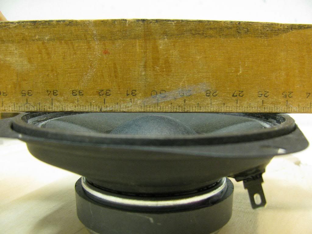
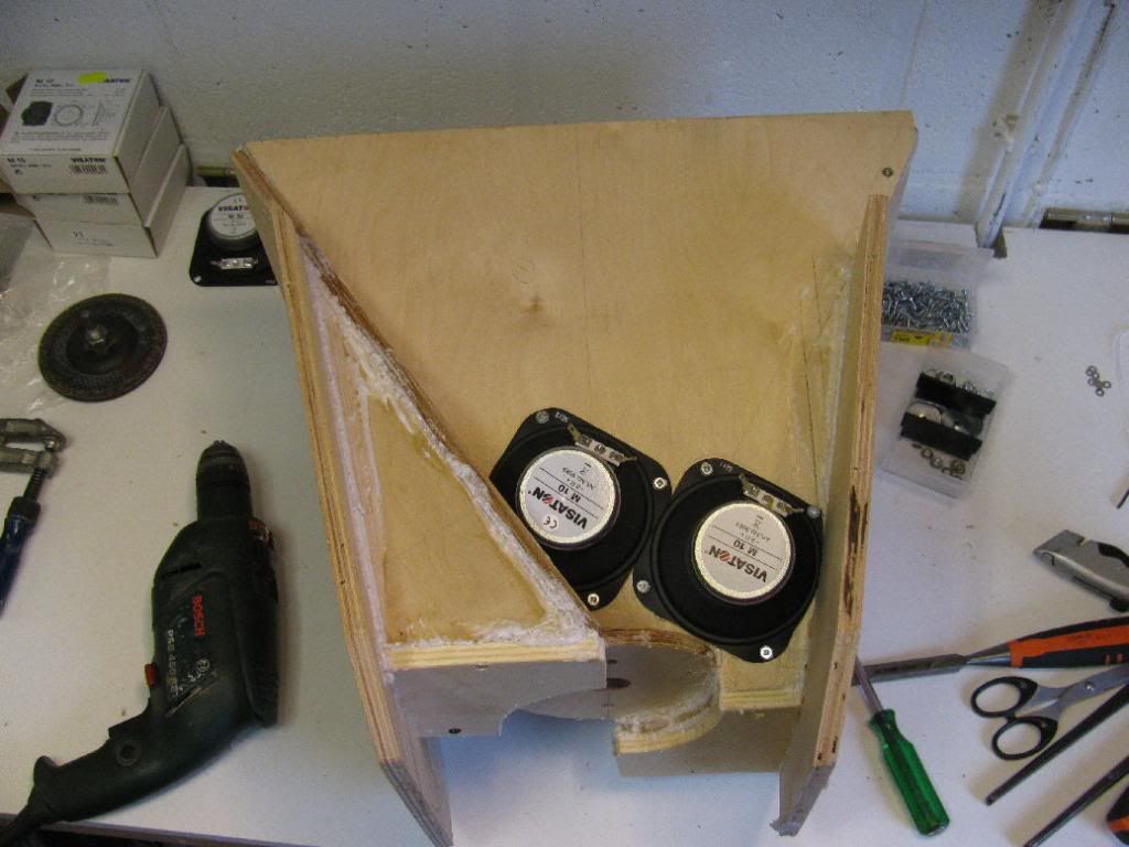
Because the dust cap of the mids is kind of big/high up to the front, I decided to route away a little wood to prevent the cap from hitting the baffle.
There's just about 2 mm of 'headroom'.
Glueing started.
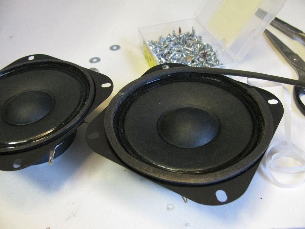
Some extra gasket tape, the M10s have rather stiff gaskets.
100th photo 😱
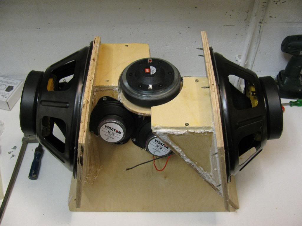
My own Tie fighter 😀.
I can't wait to fire up this second proto. I have high hopes, but I'm afraid it'll be disappointing


Woofer access:

Compression driver access:

Hatch for access to the top and bottom mids -under construction- :

This is all the wood that goes in.

Because the dust cap of the mids is kind of big/high up to the front, I decided to route away a little wood to prevent the cap from hitting the baffle.

There's just about 2 mm of 'headroom'.

Glueing started.


Some extra gasket tape, the M10s have rather stiff gaskets.

100th photo 😱


My own Tie fighter 😀.


I can't wait to fire up this second proto. I have high hopes, but I'm afraid it'll be disappointing
At the moment, none. For the front ports I calculated the minimum distance from the throat (horn area circumference > one wavelength @ xover frequency) and the cancellation notch frequency (2x distance from port to compression driver membrane = 1 wavelength). But the bottom end isn't loaded by the horn anymore (somewhere below 170Hz or so) and acts as a 4th order band pass.
I'm planning to just measure the response and see if I need to make it a 6th order band pass by adding back chamber ports... I haven't found any concrete guidelines to simulate the woofer part for a Synergy :s. And Akabak really isn't my thing😱.
I'm planning to just measure the response and see if I need to make it a 6th order band pass by adding back chamber ports... I haven't found any concrete guidelines to simulate the woofer part for a Synergy :s. And Akabak really isn't my thing😱.
I hear ya on the Akabak. I am just learning but going to shoot for the moon on my build. Great watching this unfold. I will be using BMS CD and Visaton mids. But will be using 15's for the bass section and porting the rear end also. High hopes but its fun dreaming and building. PLUS I learn more when I build then simulate.
I hope after building one of these and messing up a few times I will then understand what Bateman, SpeakerScott and JLH are all talking about. So much goes over my head.
Great work by the way.!!
I hope after building one of these and messing up a few times I will then understand what Bateman, SpeakerScott and JLH are all talking about. So much goes over my head.
Great work by the way.!!
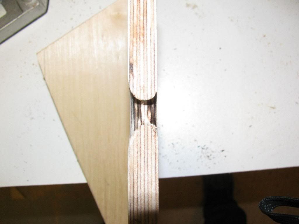
This side is ok.
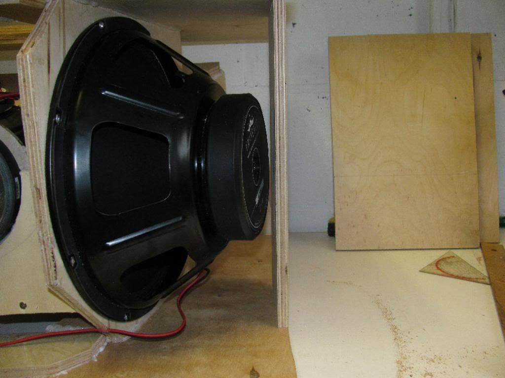
This side is not 🙁.
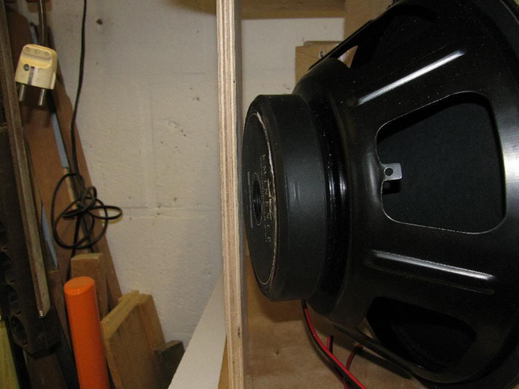
But it's not too bad. Nothing a couple of mm's routing won't fix.
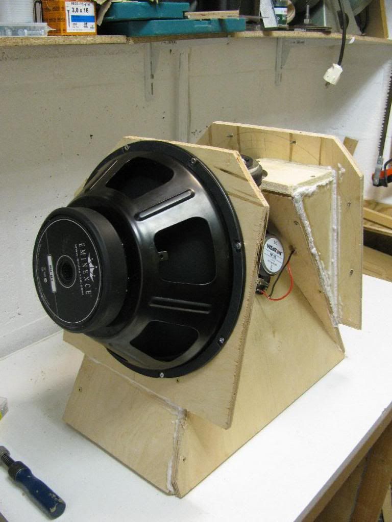
This is one of the back pieces. It needed a little cut away for the woofer to fit. And yes, I wet the wood a little. For the PU glue to expand, it needs (a little) water, and since the wood is kind of dry...
More glueing...

And now it looks like I skipped a few pictures 😱. But all I did was close the cab up. Lots of preparing the access panels, nothing too interesting.
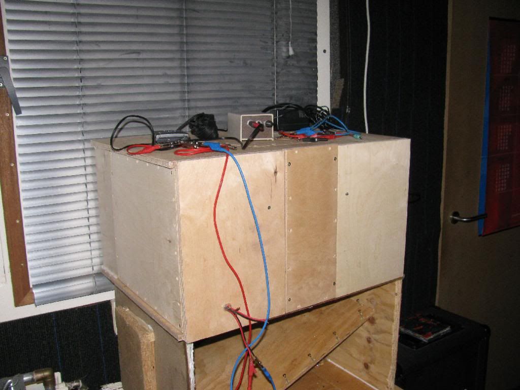
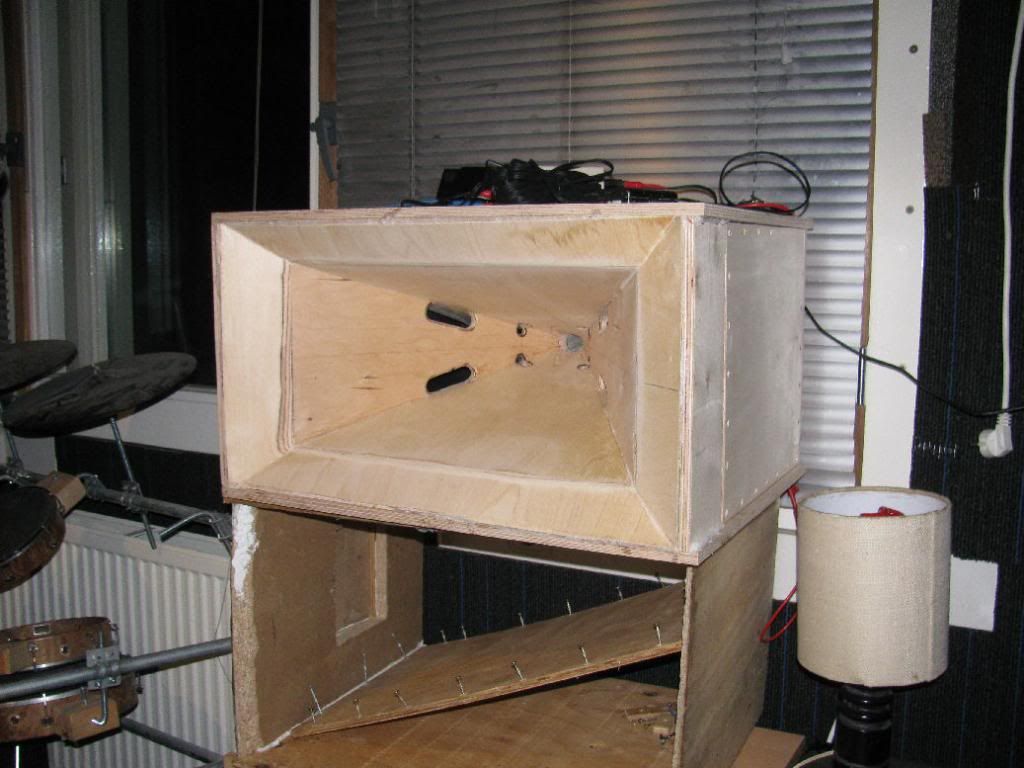
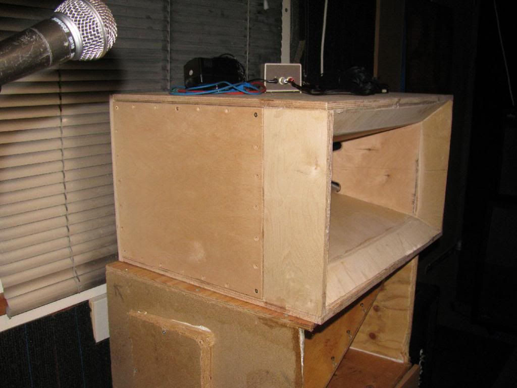
Note the empty 'box' of the first proto below it 😉.
And tomorrow: measurements . I already hooked everything up, but it's a little late now (half an hour after midnight
  ). I did fire it up with the old settings on the DCX2496, but I quickly dialed out the EQ and changed the crossover frequencies. A short test with a tone generator app on my phone led me to believe the mids now go about 80-90Hz lower and about 230Hz higher 😎, hopefully to be confirmed tomorrow by the measurements. Baut it looks...eh, sounds, promising 🙂.

This side is not 🙁.

But it's not too bad. Nothing a couple of mm's routing won't fix.
This is one of the back pieces. It needed a little cut away for the woofer to fit. And yes, I wet the wood a little. For the PU glue to expand, it needs (a little) water, and since the wood is kind of dry...

More glueing...


And now it looks like I skipped a few pictures 😱. But all I did was close the cab up. Lots of preparing the access panels, nothing too interesting.


Note the empty 'box' of the first proto below it 😉.
And tomorrow: measurements
. I already hooked everything up, but it's a little late now (half an hour after midnight ). I did fire it up with the old settings on the DCX2496, but I quickly dialed out the EQ and changed the crossover frequencies. A short test with a tone generator app on my phone led me to believe the mids now go about 80-90Hz lower and about 230Hz higher 😎, hopefully to be confirmed tomorrow by the measurements. Baut it looks...eh, sounds, promising 🙂.Here they are. Let's start with just the bare speakers.
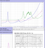
This is @1m, on axis. It looks horrible 😱. I should definitely do measurements in another room. This is what it looks like when I put the mic directly in front of the horn ("0 cm"):
Looks a lot better.
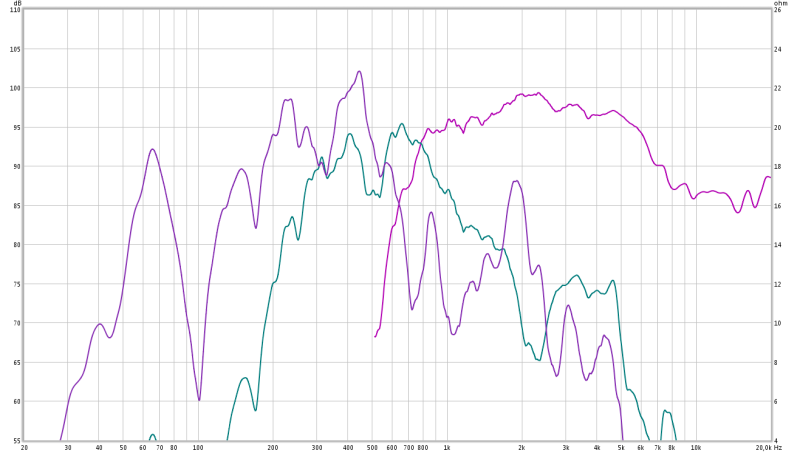
These are the impedances:
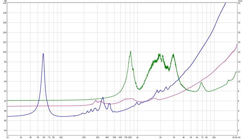
Green: BMS 4550
Purple: 6x Visaton M10
Blue: 2x Eminence Beta12-A2
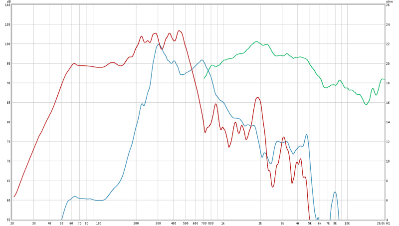
Above measurements are not related to 2.83V whatsoever. So here's the mid and woofer section at 1m and 2.83V:
Again, I need to pick another room for measuring 😡. But you get the idea.
Now I dialed in the xover on the DCX2496:
On the woofers: LP @303Hz, LR24, measured at "0cm".
On the mids: HP @ 303Hz, LR24; LP @ 1kHz, LR24, measured at "0cm".
Still the mids don't go as high as I'd like them to. I'm not sure what exactly is prohibiting them from going up to 1Khz 🙁.
But when I got the whole system dialed in, response was reasonably flat:
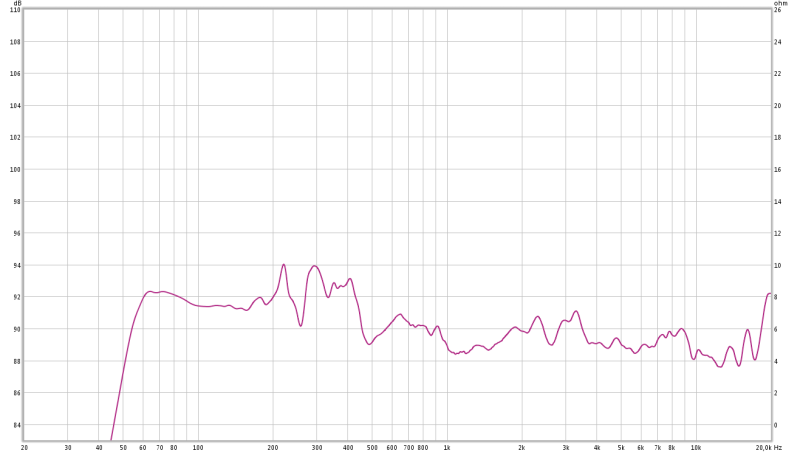
The mids can be tickled a little with eq to get up to 1kHz. I also played a little with the RTA and the pink noise generator of REW (Room Eq Wizard) and the phase adjustment options of the DEQ2496 to get the best possible match in the crossover ranges. If you don't have a DEQ or similar device and you're fiddling around with loudspeakers, you ought to buy one! To me it's like a magic box. You can tweak almost every parameter you want and you have access to a heap of fully parametric eq (as long as there is DSP processing power left).
But back to the case. What worries me is the peaked response of the woofers in the 200~500Hz range. They also appear in the impedance measurements, so there's definiely something nasty going on there 😡. I eq'ed most of it out, but eq is no miracle solution.
Also, can anybody tell me what's up with that ragged compression driver impedance plot? I thought I used enough elbow grease to smoothen the throat but it looks like I didn't. Or is it something else 😕.
I listened to various styles of music and I think the synergy concept is convincing, even though I only listened in mono. Sure, I built this version myself, but the coherent, detailed sound and effortless reproduction of high sound levels is striking. I have a set of Lynn Olson's Ariels with the D2905/95000 tweeters and I prefer the synergy, although I must admit I haven't A/B'ed them directly. I do have a pair of Mackie HR824's in the same room as where I listened to the synergy, but I didn't even bother to switch them on 😛. I will do that tomorrow, but I think I already know the outcome... But I'll try to be as objective as possible, since the Mackies are not bad either 🙄.
Cheers. And thanks for the nice comments 😉.

This is @1m, on axis. It looks horrible 😱. I should definitely do measurements in another room. This is what it looks like when I put the mic directly in front of the horn ("0 cm"):

Looks a lot better.
These are the impedances:

Green: BMS 4550
Purple: 6x Visaton M10
Blue: 2x Eminence Beta12-A2
Above measurements are not related to 2.83V whatsoever. So here's the mid and woofer section at 1m and 2.83V:

Again, I need to pick another room for measuring 😡. But you get the idea.
Now I dialed in the xover on the DCX2496:

On the woofers: LP @303Hz, LR24, measured at "0cm".
On the mids: HP @ 303Hz, LR24; LP @ 1kHz, LR24, measured at "0cm".
Still the mids don't go as high as I'd like them to. I'm not sure what exactly is prohibiting them from going up to 1Khz 🙁.
But when I got the whole system dialed in, response was reasonably flat:

The mids can be tickled a little with eq to get up to 1kHz. I also played a little with the RTA and the pink noise generator of REW (Room Eq Wizard) and the phase adjustment options of the DEQ2496 to get the best possible match in the crossover ranges. If you don't have a DEQ or similar device and you're fiddling around with loudspeakers, you ought to buy one! To me it's like a magic box. You can tweak almost every parameter you want and you have access to a heap of fully parametric eq (as long as there is DSP processing power left).
But back to the case. What worries me is the peaked response of the woofers in the 200~500Hz range. They also appear in the impedance measurements, so there's definiely something nasty going on there 😡. I eq'ed most of it out, but eq is no miracle solution.
Also, can anybody tell me what's up with that ragged compression driver impedance plot? I thought I used enough elbow grease to smoothen the throat but it looks like I didn't. Or is it something else 😕.
I listened to various styles of music and I think the synergy concept is convincing, even though I only listened in mono. Sure, I built this version myself, but the coherent, detailed sound and effortless reproduction of high sound levels is striking. I have a set of Lynn Olson's Ariels with the D2905/95000 tweeters and I prefer the synergy, although I must admit I haven't A/B'ed them directly. I do have a pair of Mackie HR824's in the same room as where I listened to the synergy, but I didn't even bother to switch them on 😛. I will do that tomorrow, but I think I already know the outcome... But I'll try to be as objective as possible, since the Mackies are not bad either 🙄.
Cheers. And thanks for the nice comments 😉.
What worries me is the peaked response of the woofers in the 200~500Hz range.
it works, cool

a sharp spike remains from the woofers, and probably could be sorted in the crossover
but looks to me like most of the broad midbass peak comes from the midrange drivers ... purple curve, 300-400hz
The 4550 impedance response does not look all that ragged to me, varies from about 8 to 16 ohms on your horn, and from 8 to 13.5 ohms on the BMS CD 90/75.Again, I need to pick another room for measuring 😡. But you get the idea.
But back to the case. What worries me is the peaked response of the woofers in the 200~500Hz range. They also appear in the impedance measurements, so there's definiely something nasty going on there 😡. I eq'ed most of it out, but eq is no miracle solution.
Also, can anybody tell me what's up with that ragged compression driver impedance plot?
If you did not short the outputs of the other drivers while taking your impedance and frequency response tests, that would be responsible for some of the peaks and dips.
The 10" look like they will need some "underlap" (cross them lower than 300 Hz) to smooth the response, as well as some out of band EQ, but you really need to do some outdoor measurements away from boundaries to see what the response is at a few meters.
And don't give us some whimpy remark about "it's too cold for outdoor testing", I came from Minnesota 🙂.
Looks like it's shaping up OK!
Attachments
And don't give us some whimpy remark about "it's too cold for outdoor testing", I came from Minnesota 🙂.
Bold words from someone who moved away to....the desert isn't it? 🙄 lol
I've been following this thread for a while, excellent work & documentation!
Very nice work! 
I think the ports on M10 may be too small as the ratio of that port by the volume behind the port controls cutoff freq. Maybe enlarge it? Work on a smooth finish on throat and paint it and sand it. That may help with BMS response.
I think the ports on M10 may be too small as the ratio of that port by the volume behind the port controls cutoff freq. Maybe enlarge it? Work on a smooth finish on throat and paint it and sand it. That may help with BMS response.
I'm not exactly sure which purple curve you mean. There are several...but looks to me like most of the broad midbass peak comes from the midrange drivers ... purple curve, 300-400hz
 ...
...What I meant with ragged are the tiny sawtooth ripples from about 950Hz to 3k, not the general trend. These seemed a bit odd to me. I didn't short the other drivers, but they were still hooked up to the power amp, so that should suffice.The 4550 impedance response does not look all that ragged to me, varies from about 8 to 16 ohms on your horn, and from 8 to 13.5 ohms on the BMS CD 90/75.
If you did not short the outputs of the other drivers while taking your impedance and frequency response tests, that would be responsible for some of the peaks and dips.
The 10" look like they will need some "underlap" (cross them lower than 300 Hz) to smooth the response, as well as some out of band EQ, but you really need to do some outdoor measurements away from boundaries to see what the response is at a few meters.
Thanks for your suggestions. I will play around with the crossover and eq settings, but I was hoping to design a passive crossover so I wouldn't be needing 6 amp channels to power two boxes
. With the DCX2496 it's as easy as turning a knob to go from LR24 to LR48, it literally is, but with passives...On the first proto the ports were a good bit larger in diameter. And as you can see in the measurements of the first prototype I posted before they didn't go any higher either. They actually dropped off earlier 🙁. So I'm a bit hesitant to f**k up the nice rounded ports unless I'm >50% sure it would help, but perhaps just using a slightly larger drill bit won't be too invasive.Very nice work!
I think the ports on M10 may be too small as the ratio of that port by the volume behind the port controls cutoff freq. Maybe enlarge it? Work on a smooth finish on throat and paint it and sand it. That may help with BMS response.
Do you think the BMS response is bad? I was talking about the impedance plot...
And thanks again for the compliments.
I'm not exactly sure which purple curve you mean. There are several
I will try to illustrate with this
Attachments
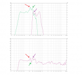
I will try to illustrate with this
Ah, I see. But I'm not sure that is the case. I would have to play around with the xover settings to find out.
Ok, I did some measurements outside. This is what I have to deal with...
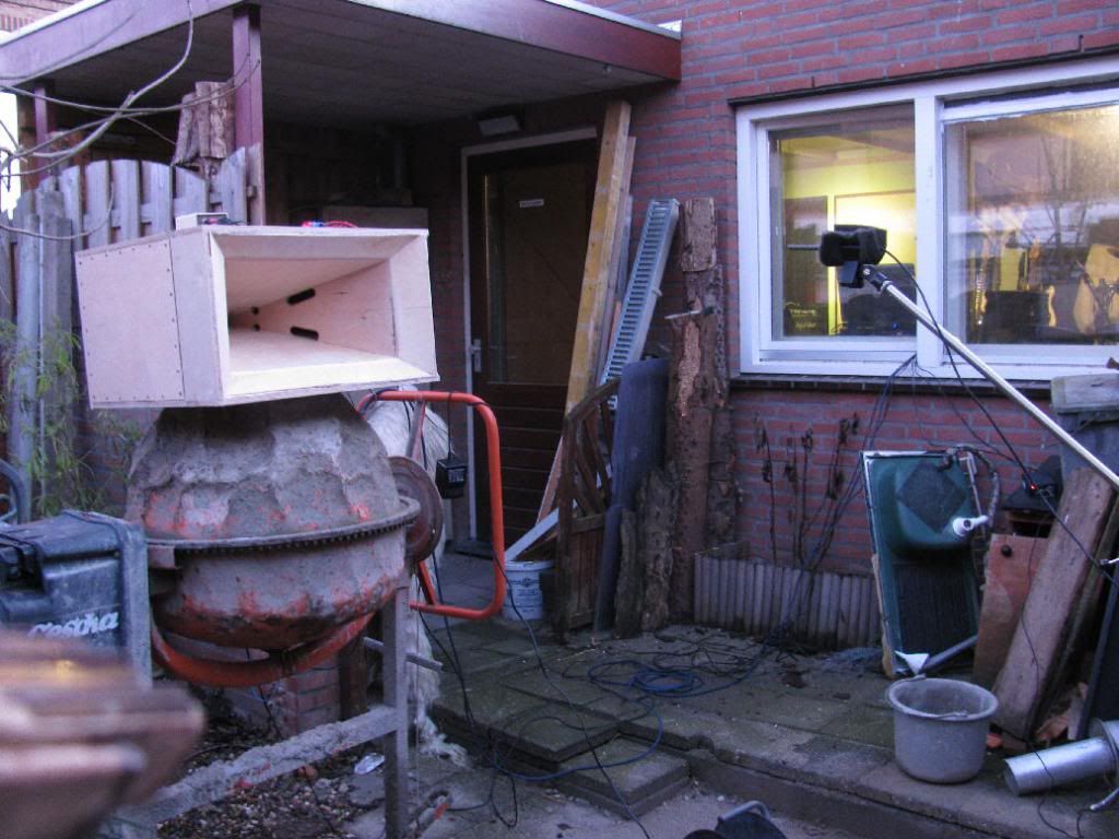
Don't mind the mess 😱. Home improvement takes a lot of time&money...
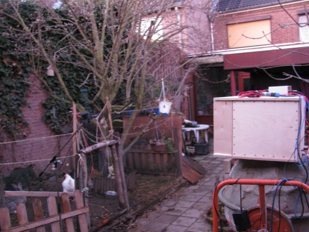
Anyway, here are the results. I did two separate measurements, the second with the speaker slightly rotated to the left, as seen in the first photo above and the mic repositioned to be on axis.
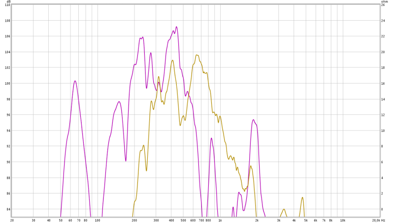
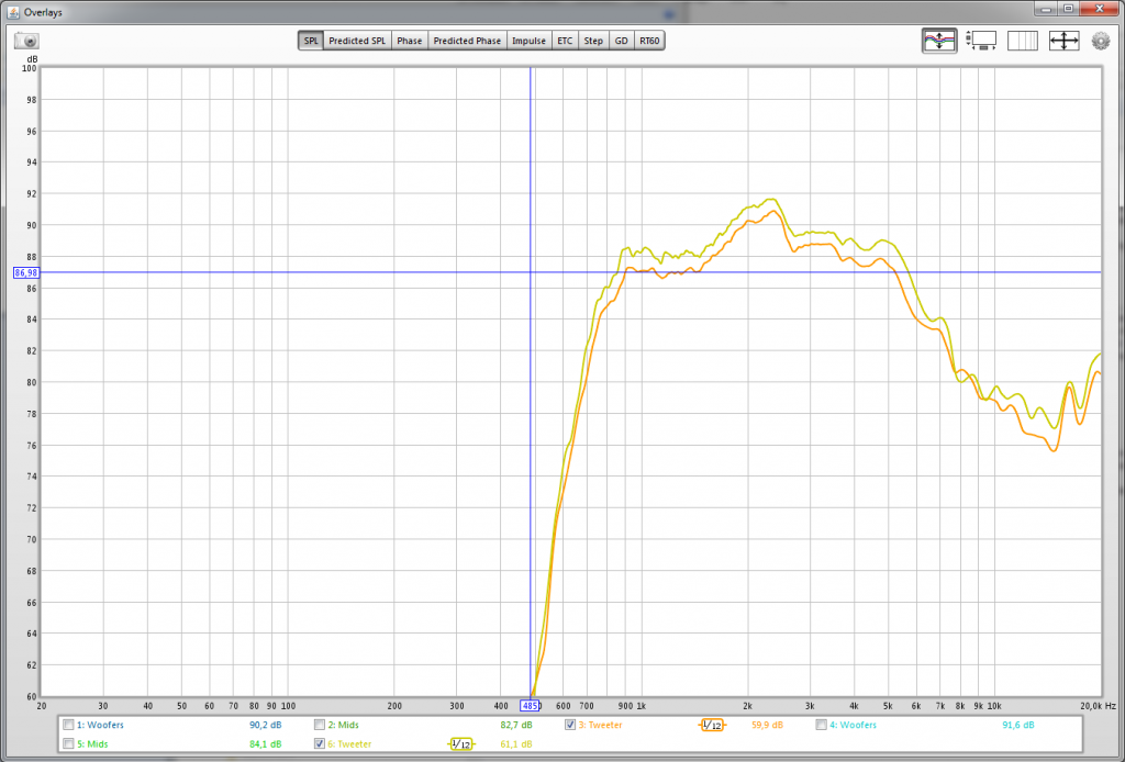
Here are the two compression driver measurement responses:
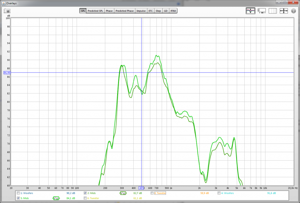
The mids...
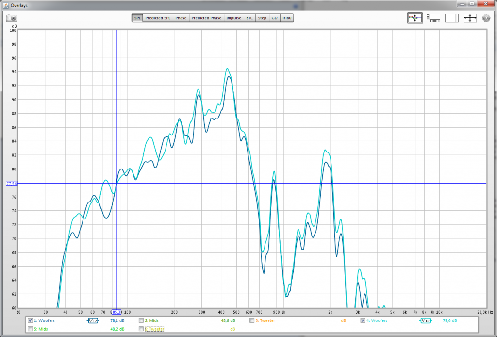
...and the woofers:
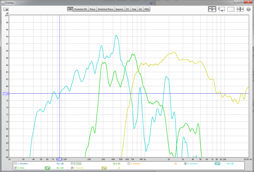
Here's an overlay of one set of measurements:
And the phase responses, all six of 'em:
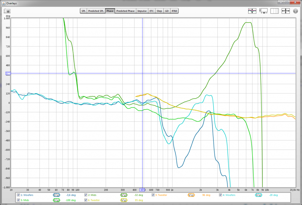
Blue: woofers, green: mids, yellow: compression drivers.
The compression driver behaves excellent in all my measurements.
The mids measure slightly different, though in both cases the mic was @ 1m and on-axis. Well, perhaps a few cm more or less than 1m.
The woofer section measures different as well. At some frequencies the difference is more than 4dB. For example @ 140Hz. There was a slight volume difference, I loaded a different setting on the DCX in between the two measurements . But overall the curves are approximately at the same volume.
And what happened with the phase response of the mids 😕.
I should have taken some measurements from farther away, 2 or 3 meters or so 🙁. But I already tore the setup down and it's quite dark now, so that's not going to happen today anymore.


Don't mind the mess 😱. Home improvement takes a lot of time&money...
Anyway, here are the results. I did two separate measurements, the second with the speaker slightly rotated to the left, as seen in the first photo above and the mic repositioned to be on axis.
Here are the two compression driver measurement responses:

The mids...

...and the woofers:

Here's an overlay of one set of measurements:

And the phase responses, all six of 'em:

Blue: woofers, green: mids, yellow: compression drivers.
The compression driver behaves excellent in all my measurements.
The mids measure slightly different, though in both cases the mic was @ 1m and on-axis. Well, perhaps a few cm more or less than 1m
.The woofer section measures different as well. At some frequencies the difference is more than 4dB. For example @ 140Hz. There was a slight volume difference, I loaded a different setting on the DCX in between the two measurements
. But overall the curves are approximately at the same volume.And what happened with the phase response of the mids 😕.
I should have taken some measurements from farther away, 2 or 3 meters or so 🙁. But I already tore the setup down and it's quite dark now, so that's not going to happen today anymore.
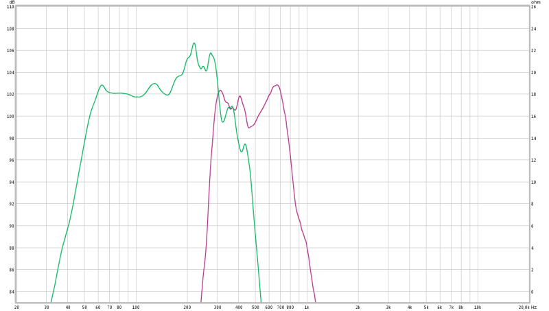
I 100% sure the 250hz dip between the two peaks is caused by the crossover
Well, the crossover was set at 303Hz, LR48, so quite steep. And I set a couple of eqs to tame the peaks at 220 and 300 Hz... I'll mess around some more tomorrow 🙂
- Status
- Not open for further replies.
- Home
- Loudspeakers
- Multi-Way
- Synergy with BMS 4550, Visaton M10 and ...