Thanks ! How did you choose your pattern size?...sorry if i'm forgetting here. It sounds like you went for a pretty narrow vertical pattern?Very nice results. I look at your horn on the screen, then glance over at mine. Yours is only 20% wider but almost twice as tall. So I'm familiar with the polar response limitations.
I don't really have a set listening position, so i have been trying to get polars as smooth as possible, at least within +/- 30 deg horiz.Like you I forego a secondary flare, just equalizing in room for my primary listening position, knowing the listening window width could be improved by a secondary flare but not caring. Is your decision based on similar thinking or are you saying that +/- 3db FR ripple is not or is just barely audible?
It's been my experience though, that if polar variations are within a +/- 3dB FR ripple, i get a sweet spot window about 60 degrees wide that i can only hear a difference within with the most careful listening. Almost have to work to hear a difference in the large 60 degree window.
Since primary flares alone, and some dsp work, can keep polar FR ripple within the 3dB range, i'm like "why bother with secondary flares?"
Hope that made sense.
Shifting gears.... stereo is fun after being away from it for a while. These relatively big builds image a little better than i expected, and certainly better than expected over a pretty wide area. Maybe that's were good polars really come into play? Maybe more so than effecting room response? Dunno....
Sure, I'll find a good representative set and post them.I'd be curious how the polars differed.
The issue secondary flares have helped the most with, has been ripple in the 1-2k area...(not where you want it huh?)
I've found if i tune the syns at 10-15 degrees off axis, that usually centers the ripple around flat reponse, such that on-axis dips one way, and 30 degrees goes the other way, but all stays tolerable.
SPL was pretty high when measuring polars, I mainly test outdoors at about 9ft from speaker in high ambient noise, so i keep signal turned up. Usually 90dB+ at mic..Perhaps the sound didn't change because off axis the SPL was so low it didn't contribute meaningfully to the combined SPL at the listening position? So a little more ripple might not be audible? I just don't know how low that off axis energy needs to be to behave this way.
Indoors, same story....I like SPL and dynamics...the rooms gets a lot of energy.
Mine was 90x45. 90 because it was a corner horn and I wanted to fill the room. 45 because I didn't know any better at the time.Thanks ! How did you choose your pattern size?...sorry if i'm forgetting here. It sounds like you went for a pretty narrow vertical pattern?
I don't really have a set listening position, so i have been trying to get polars as smooth as possible, at least within +/- 30 deg horiz.
It's been my experience though, that if polar variations are within a +/- 3dB FR ripple, i get a sweet spot window about 60 degrees wide that i can only hear a difference within with the most careful listening. Almost have to work to hear a difference in the large 60 degree window.
Since primary flares alone, and some dsp work, can keep polar FR ripple within the 3dB range, i'm like "why bother with secondary flares?"
Hope that made sense.
Shifting gears.... stereo is fun after being away from it for a while. These relatively big builds image a little better than i expected, and certainly better than expected over a pretty wide area. Maybe that's were good polars really come into play? Maybe more so than effecting room response? Dunno....
OK so you are tolerating +/- 3db, which is consistent with my experience. I agree why bother, indeed its OK to accept a compromise you can see in measurements, if you can't hear the difference.
I mean how did the SPL drop off as you went off axis?SPL was pretty high when measuring polars, I mainly test outdoors at about 9ft from speaker in high ambient noise, so i keep signal turned up. Usually 90dB+ at mic..
Indoors, same story....I like SPL and dynamics...the rooms gets a lot of energy.
Oh, ok. Not much within the horn pattern.I mean how did the SPL drop off as you went off axis?
Here's a set from the 75x60.
Blue is 10 degrees off-axis and was the tuning axis.
Dark green 0 deg. Orange is 20 deg. Red is 30 deg.
So all those traces fit within the horizontal horn pattern. Little drop in SPL.
Light green 40 deg, and purple 50 deg, are outside the horns pattern, but still plenty of SPL i think.

I think I will need to build a 3 way too based on your experience. Then I could get rid of the separate midbass part of my horn system and save some front space (height is the limit at the moment, the 4 way stack was floor to ceiling at one point of time🙂 )
Indeed! As I understand it, the goal here is to reactance annul it as much as possible with just the right amount of front and rear compression loading to tightly control movement and the 'sharp' horn corners where the vents are is a low pressure point, so acts as scavengers to efficiently purge or block the woofer's low pass filter [LPF] chamber due to the horn's pressure waves that combined creates a quasi-6th order BP.Maybe the compression, right in the weakest area of the cone from the motor's control viewpoint, makes for a less dynamic response. It makes sense to me that ports in the corners beg for a really stiff *** suspension
IOW, your's 'sounds' to me like it's designed more like a typical BP4, same as I first thought of when Tom gave me some hints of his new invention long before seeing the original Unity horn with its corner vents that based on my experience with race car aerodynamics didn't seem a good idea overall for audio since I assumed he was wanting to keep them out of the horn's 'slipstream', but when I queried him on one of the earliest threads he confirmed in testing it was the better solution, though of course with no further details.
It took awhile to sink in as to probably why and then only because I was reminded that as one 'crusty' old cinema/pro sound horn designer long ago remarked: "If it doesn't sound smooth as a baby's bottom, it's fundamentally flawed, if you catch my drift" and Tom being prosound oriented, it's probably as ideal an acoustic balancing act as practical to extract [squeeze] the max acoustic power out with the least diaphragm movement, hence least distortion.
Amazing how much insight [in retrospect] can be crammed into such an innocuously simple statement.
I think I will need to build a 3 way too based on your experience. Then I could get rid of the separate midbass part of my horn system and save some front space (height is the limit at the moment, the 4 way stack was floor to ceiling at one point of time🙂 )
You know pelanji, for a fat two years i dedicated myself to the the idea that a two way (counting coax CD as one way) is the way to go. Straight from CD to large low mids. 8 versions. And it seemed to be, sounding better (to me) than any other stuff i heard at dealers / shows.
Then i tried adding the small mids, and whoola...new found clarity.
That has mattered more to clarity than all the driver selections, port locations, horn size/pattern selections, mouth terminations, etc...that i've tried.
Hey here's a laugh for everyone on me....
Last week i put one of these just finished 90x60 guys on the spinorama to set up an initial indoor tuning. Boxes are all glued up, and it's the first time i ever made a stereo pair right from the gitgo without prototyping.
I start tuning with the VHF section of the coax CD then HF section, like always since the CD establishes the reference ToF.
I do all this from my office, with XLR's running out to my test/listening room.
Moving next to the small mids...I'm like why is their output so low? Maybe i miss-wired them, needing the four 16 ohm guts to be in parallel.
So I head to the test room thinking to check wiring....and holy sheep shite !!!
I forgot to put their ports into the horn 😳
I can be such a mellon head.......
Fortunately, a non fatal, easy to fix oversight...
Indeed! As I understand it, the goal here is to reactance annul it as much as possible with just the right amount of front and rear compression loading to tightly control movement and the 'sharp' horn corners where the vents are is a low pressure point, so acts as scavengers to efficiently purge or block the woofer's low pass filter [LPF] chamber due to the horn's pressure waves that combined creates a quasi-6th order BP.
IOW, your's 'sounds' to me like it's designed more like a typical BP4, same as I first thought of when Tom gave me some hints of his new invention long before seeing the original Unity horn with its corner vents that based on my experience with race car aerodynamics didn't seem a good idea overall for audio since I assumed he was wanting to keep them out of the horn's 'slipstream', but when I queried him on one of the earliest threads he confirmed in testing it was the better solution, though of course with no further details.
Thank for all that GM, and it makes sense.
If the major purpose of ports in the corners is to milk all possible SPL, I'm ok letting go of that.
If they help make a higher order acoustic low pass filter (than ports in the center), I'm ok with that too because i use steep 96 dB/oct xovers that diminish that benefit.
If they help improve polar performance of the CD or small mids by being less interfering, I'm not ok loosing that. But so far, it doesn't seem to matter much to polars.
Ok, as a result of low driver port location discussion, i set up my most basic port test box again, which is simply a small sealed box that i can lay a plate with port holes over the driver wherever desired.
Nothing fancy... just this sitting on the floor.
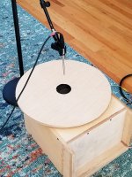
Driver is 10fe200. Port is 2 7/8" dia.
Blue trace is port centered on cone. Red is port edge over surround edge.
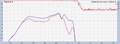
It's just a one port test. I've had similar results trying different sizes and number of ports.
A single centered port has always had the relatively best overall looking trace.
Trying to dig a little deeper, went to REW's burst generator and scope.
Here's edge first, then centered.
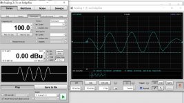
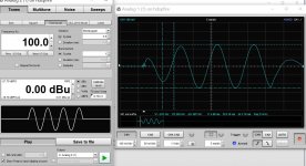
Peak to peak voltage, gives centered +2.2 dB.
REW's peak SPL meter gave +2.3 dB.
Both of which tie closely to Smaart's magnitude trace, i think.
Anyway, thought this might be of interest...and i must admit, i'm still looking for reasons to put low ports in the corners...
Nothing fancy... just this sitting on the floor.

Driver is 10fe200. Port is 2 7/8" dia.
Blue trace is port centered on cone. Red is port edge over surround edge.

It's just a one port test. I've had similar results trying different sizes and number of ports.
A single centered port has always had the relatively best overall looking trace.
Trying to dig a little deeper, went to REW's burst generator and scope.
Here's edge first, then centered.


Peak to peak voltage, gives centered +2.2 dB.
REW's peak SPL meter gave +2.3 dB.
Both of which tie closely to Smaart's magnitude trace, i think.
Anyway, thought this might be of interest...and i must admit, i'm still looking for reasons to put low ports in the corners...
You're welcome!
Thanks for the continued sharing as you move up the MEH's design theory 'Totem Pole'! 😀
😀
Again, as I understand it; you're right, there's more to the DSL MEH's 'puzzle', but TTBOMK we're down to where Tom currently 'stands mute', so 'color' me done WRT posting anything more technical beyond it's apparently all hiding in 'plain sight' and that not disparaging in any way yours/others (massive) efforts to date, the few DIY ones I've browsed are all fundamentally wrong. 🙁
Not that it matters in the scheme of things of course as proven by you and others since the advent of affordable DSP allows anyone to do a good/excellent job of turning a 'mishmash' of parts into a high performance MEH.
Thanks for the continued sharing as you move up the MEH's design theory 'Totem Pole'!
 😀
😀Again, as I understand it; you're right, there's more to the DSL MEH's 'puzzle', but TTBOMK we're down to where Tom currently 'stands mute', so 'color' me done WRT posting anything more technical beyond it's apparently all hiding in 'plain sight' and that not disparaging in any way yours/others (massive) efforts to date, the few DIY ones I've browsed are all fundamentally wrong. 🙁
Not that it matters in the scheme of things of course as proven by you and others since the advent of affordable DSP allows anyone to do a good/excellent job of turning a 'mishmash' of parts into a high performance MEH.
HAhaa, yeah 😀 But I think it is a good thing in a way that the word is now out and people actually trying out what matters and what not 😀I'm beginning to think CEA2034 has got us all drunk on working for perfect polars ....haha
Healthy thing! Reality is quite complex, but the fundamental bottom line important stuff is often rather simple and I think imagination gets long way to understanding things and leads to insight and development even if it wasn't exactly scientific! Keep on going!🙂 Check out Richard Feynman related videos from Youtube, very inspiring!I have this imagination, that the port area over the surrounds actually varies depending on the position af the piston/cone, whether its pulling in (negativ current) or pushing out (positiv current), like the cone is partially closing the port if taken to extremes! The air can not pass as freely over the surround and in/out as in the middle over the voice coil!?
Simple test of "single ideal reflection" that combines to direct signal at ear attached. It looks like without attenuation 6dB peaks occur, naturally. To get the interference pattern down to +/-3dB the reflection needs to be attenuated about 10dB. Maybe there is proper math to this, but the very quick test in simulator is visual and thus easy to understand so I won't bother with math 😀I'd be curious how the polars differed. Perhaps the sound didn't change because off axis the SPL was so low it didn't contribute meaningfully to the combined SPL at the listening position? So a little more ripple might not be audible? I just don't know how low that off axis energy needs to be to behave this way.

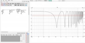
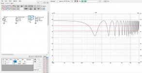
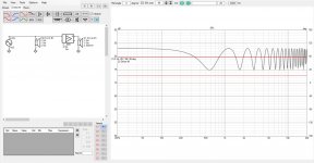
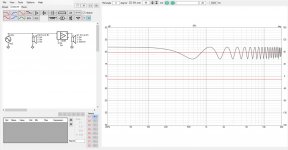
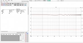
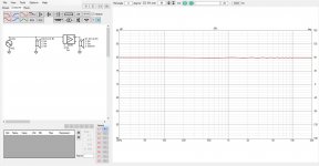
If reflection point is close to source, then there is not much attenuation through air since path length is not that much longer than with direct sound, and heavy narrowing in directivity towards reflection point would be needed to reduce "problem". However, if the path length through the reflection is double to direct sound path length to ear then there is already 6db attenuation on the reflection without any help from speaker directivity. Add some kind of speaker directivity, count in some attenuation on the wall, and -10dB is not too hard to achieve in reality.
Nominal dispersion of 90 degrees horizontal would mean -6dB towards 45 degree angle. If such speaker is toed in (horizontal) reflection point could be at 90 degrees or more, which gets to attenuation around -20dB towards reflection point, which gets the interference to +/-1dB. If there is problem with reflections in this simplified thought experiment in context with full range waveguide, it is with floor and ceiling since those would have relatively low angle towards reflection.
Last edited:
Devil is in the detail! Very good products that have been optimized for particular application would have all (at least most) the details inline with the goal and ours might differ and require different approach for better outcome if the goal was something else (than max SPL in this case).You're welcome!
Thanks for the continued sharing as you move up the MEH's design theory 'Totem Pole'!😀
Again, as I understand it; you're right, there's more to the DSL MEH's 'puzzle', but TTBOMK we're down to where Tom currently 'stands mute', so 'color' me done WRT posting anything more technical beyond it's apparently all hiding in 'plain sight' and that not disparaging in any way yours/others (massive) efforts to date, the few DIY ones I've browsed are all fundamentally wrong. 🙁
Not that it matters in the scheme of things of course as proven by you and others since the advent of affordable DSP allows anyone to do a good/excellent job of turning a 'mishmash' of parts into a high performance MEH.
It would be fun to see what Tom has to say on this 😀
Thanks mark, GM, others, for digging deeper than the surface!
Those are quite a bit better than I was able to measure in room, probably because I was measuring in room.Oh, ok. Not much within the horn pattern.
Here's a set from the 75x60.
Blue is 10 degrees off-axis and was the tuning axis.
Dark green 0 deg. Orange is 20 deg. Red is 30 deg.
So all those traces fit within the horizontal horn pattern. Little drop in SPL.
Light green 40 deg, and purple 50 deg, are outside the horns pattern, but still plenty of SPL i think.
View attachment 1006306
My turn to say you're welcome ! Glad to be able to be a part of the group trying to 'climb the pole' 🙂Thanks for the continued sharing as you move up the MEH's design theory 'Totem Pole'!😀
I totally agree there comes a point where things shared by an inventor in the business, like Tom, need to be taken as a personal gift and not passed on to the world at large. It's the right way to be and show thanks and respect imho.Again, as I understand it; you're right, there's more to the DSL MEH's 'puzzle', but TTBOMK we're down to where Tom currently 'stands mute', so 'color' me done WRT posting anything more technical beyond it's apparently all hiding in 'plain sight' and that not disparaging in any way yours/others (massive) efforts to date, the few DIY ones I've browsed are all fundamentally wrong. 🙁
I read Tom mention the low pressure zone in the horn corners, on another forum recently.
I had a horn in the making without any ports in it, so i drilled 1/4" holes to stick a mic in various locations to try to see what measurements of the CD might show....corners vs center, etc. I didn't measure any difference, looking at impulse or transfers....so i dropped continuing on. Maybe that's the wrong way to measure....?
Yep, DSP is certainly helping make reasonable acoustic designs, easier to achieve excellent results.Not that it matters in the scheme of things of course as proven by you and others since the advent of affordable DSP allows anyone to do a good/excellent job of turning a 'mishmash' of parts into a high performance MEH.
That said, i think most all of us intuit that the better the acoustic design, and the less the need for DSP....makes for all the better. (with the exception of complementary linear phase xovers whenever usable haha....should be my mantra lol)
You bet tmuikku, and thank you and nc535 all all the others that continue to explore deeply with simulations etc.Thanks mark, GM, others, for digging deeper than the surface!
I think advancing DIY onward is like a bird that needs two wing to fly. One wing is theoretical, at the edge exploration/simulation. And the other wing is pragmatic implementation and testing.
Yeah, measuring a MEH in a room is a real pain and crap shoot, imo. (MEH or any speaker, haha)Those are quite a bit better than I was able to measure in room, probably because I was measuring in room.
The graph posted was outdoors off a deck at about 3m.
One new (for me) indoor measuring technique that is showing promise at close range is:
With speaker on spinorama and mic at about 1m, turn on transfer measurement with temporal averaging, and rotate speaker back and forth within the angle you'd like to average measurements for. I've been using about 10 sec of back and forth, within +/- 30 deg. ARTA and Smaart both handle temporal averaging.
This has allowed perfect correction for that type average. I'm waiting for a good chance to compare this against regular outdoors.
Hi Mark
Any resent developments?
If I am not mistaken, you have raised the crossover from the mid´s to the CD to 900 Hz!? I read it in the camplo-thread.
Did you move the mid´s ports closer to the CD or is it still as in the "original" SYN9v3?
That makes me optimistic, as I have gotten my hands on a pair of used Faital Pro HF1440´s. I guess they will work better at 900Hz than down to 650-700Hz?
Steffen
Hi Steffen,
SYN9v3 remains unchanged....I love it. I continue to be amazed at the clarity, never knew how witty many of the songwriters are LOL.
I've just started a 3rd one, to make a LCR setup....might try to see if i can get some bass-reflex ports into it.....but it will have to work with the ports as is, too happy to start over.
Yes, i'm crossing mids to CD at 900Hz.
I've wanted to get a HF1440 to try on it, at 900-1110Hz...i think it should work fine.
The first SYN9 prototype with nothing but 4fe35's and 10fe300s (and either of my coax CDs), sounded completely awesome.
I don't think the high $, low reaching CD's are needed.
I'm thinking for under $500 for drivers per box, which includes the HF1440, folks could have a super duper sounding MEH.
- Home
- Loudspeakers
- Multi-Way
- SYN 9: a change in direction