mikeb! Did you build the schematic which you posted at post #33?
the sound? more smooth? perhaps 2 diff stage
I'm using ordinary topo but vas current above 10mA instead of 5mA .In the sim , 2nd is about 100uV .Its sound is quite good .I like this kind of sound .However ,it has a bit noise ,not seperate complete . Perhaps a PSRR of CFP input stage is higher than a normal input stage
my amp = a normal diff input with 1mA (2mA current source) , darlington vas without cascode , a normal darlington output stage with 2.1V bias🙂
Hi thanh !
I did not build the version with nested diffamps, only the normal
folded cascode. But i didn't really like the sound. The last i've
built was the cascoded vas, nearly perfect, but only nearly...
At the moment i am doing theory only.
Yours is now cfp-input with darlingtonvas ?
Mike
I did not build the version with nested diffamps, only the normal
folded cascode. But i didn't really like the sound. The last i've
built was the cascoded vas, nearly perfect, but only nearly...
At the moment i am doing theory only.
Yours is now cfp-input with darlingtonvas ?
Mike
Hi, Mike,
What have you find with the phase shifts, FM-AM-PM distortion? Are you getting that all? I have difficulties with calculus. 😀
Can those explained in simple words?
What have you find with the phase shifts, FM-AM-PM distortion? Are you getting that all? I have difficulties with calculus. 😀
Can those explained in simple words?
Hi lumanauw !
Not too much i fear... But IMD is a very importing thing, and explains
your problems with amps sounding bright, where increasing
openloopbandwidth removed this.
At the moment i am investigating the effect of different distortiontypes
on music. Maybe you have seen my posting in the other thread ?
The PIM-thing is next to investigate...
Mike
Hi, Mike,
You said about changing IMD to Distortion Bomb or something like that?😀
I still dont know what is IMD.
You said about changing IMD to Distortion Bomb or something like that?😀
I still dont know what is IMD.
Hi lumanauw !
Think of IMD like what unlinearity really does to audiosignals.
THD describes unlinearity itself, IMD the results of unlinearity.
The problem is, that imd/thd creates high order harmonics that
can't be compensated by feedback if openloopbandwidth is not
high enough. For example, you have a signal containing only freqs
below 5khz. Openloopbandwidth is up to 5khz. But imd/thd creates
frequencies above the 5khz that are not compensated by feedback.
Now you have all audible artifacts resulting from openloopdistortion,
as none of them are compensated. There is your bright sounding amp !
So, openloopbandwidth over the whole audioband is a must have.
An example for IMD: You have a signal 3+4khz, apply distortion to
it (2nd harmonic only). Now you would expect harmonics at 6+8khz,
but you have bigger harmonics at 1+7khz. with 3rd harmonic
distortiontype you have these harmonics at 10+11khz.
And my tests with music showed that 3rdharmonic distortion leads
to heavy imd, 2nd harmonics dont.
I hope i did not talk crap,
Mike
Hi, Mike,
Aha, I get it. Thanks for the explenation in simple words.
But I dont understand this :
What is the connection between IMD and THD?
So, distortion can make "unfeedbackable" distortions if the OLbandwith is too low. Maybe it is what the harmonics makes that matters, not the harmonic itself (3rd harmonic is notorious, maybe because it makes other harmonic in high frequencies).
Mike, Mr. JC said about 5th and 7th distortions that should be examined clearly. What is happening with these harmonics?
The problem is, that imd/thd creates high order harmonics that can't be compensated by feedback if openloopbandwidth is not high enough. For example, you have a signal containing only freqs below 5khz. Openloopbandwidth is up to 5khz. But imd/thd creates frequencies above the 5khz that are not compensated by feedback. Now you have all audible artifacts resulting from openloopdistortion, as none of them are compensated. There is your bright sounding amp !
So, openloopbandwidth over the whole audioband is a must have.
Aha, I get it. Thanks for the explenation in simple words.
But I dont understand this :
Think of IMD like what unlinearity really does to audiosignals. THD describes unlinearity itself, IMD the results of unlinearity.
What is the connection between IMD and THD?
And my tests with music showed that 3rdharmonic distortion leads to heavy imd, 2nd harmonics dont.
So, distortion can make "unfeedbackable" distortions if the OLbandwith is too low. Maybe it is what the harmonics makes that matters, not the harmonic itself (3rd harmonic is notorious, maybe because it makes other harmonic in high frequencies).
Mike, Mr. JC said about 5th and 7th distortions that should be examined clearly. What is happening with these harmonics?
Hi, Mike,
Something is confusing me. What makes the feedback effective only in the region of OL bandwith area? Shouldn't feedback effective in the whold Closed Loop area?
Something is confusing me. What makes the feedback effective only in the region of OL bandwith area? Shouldn't feedback effective in the whold Closed Loop area?
Hi !
The point is, that with limited ol-bandwidth, openloopgain drops
within audioband. Lower openloopgain reduces feedback.
Lets say, you have closedloop gain of 1:45, openloopgain 1:4500,
gives feedback 1:100. (Normally you use DB's)
But with limited olbandwidth openloopgain dropped to 1:90 at 10 khz,
giving feedback 1:2 at 10khz.
These numbers are examples only, very unrealistic and exaggerated.
An amp with olgain of 4500 normally has high bandwidth.
What i have understood, is that imd is what you really get with
distortions on a complex signal. This means if thd is null over the
whole audioband you have no imd. (Other distortiontypes ignored)
I had no close look at 5th&7th harmonics yet.
Mike
no, a normal input with darlingtonvasYours is now cfp-input with darlingtonvas ?
In the sim, my circuits is stable with 47p compensation capacitor but in the real circuit i must use 100p .But with 100p comcapacitor olbw is around 3kz
Hi thanh !
Have you tried smaller resistors in the vas to ground ?
These reduce openloopgain and increase bandwidth.
Another possibility is to not use cdoms, and instead put these
100pF in paralell to the resistors.
Mike
Have you tried smaller resistors in the vas to ground ?
These reduce openloopgain and increase bandwidth.
Another possibility is to not use cdoms, and instead put these
100pF in paralell to the resistors.
Mike

No, i mean like the 100k in my folded cascode. It's a fixed resistive
load to vasoutput.
I don't understand your 1nF, is it connected to collector of 1st bjt ?
Or is it a RC to supplyvoltage ?
How big is your feedbackcap ? (The one in the feedbacknetwork)
I think your 470uF is risky, charging this one at startup will give
very big current through the vas, this might blow outputstage,
and if these are not matched (assuming symetrical design), you get
big startupthump.
oh! i see🙂 I used 10k instead of using 100k .The result is bad with a large of distortion. But in a normal vas 10k get a good result .I remark that folded cascode is not like some normal circuit
mikeb! with 470u ,the distortion is increased by many times
no . It is 2 pole compensate network .I use 2 capacitor 100p and 1nI don't understand your 1nF, is it connected to collector of 1st bjt ?
mikeb! with 470u ,the distortion is increased by many times
thanh said:I remark that folded cascode is not like some normal circuit
...
with 470u ,the distortion is increased by many times
Yes, folded cascode is a bit different...
Hmm, if the distortion is increased by many times with 470u, why use it ?
I think this was a typo, it should increase openloopgain dramatically,
but also decrease bandwidth...
From what i've learned the last days/weeks, openloopbandwidth is
very important. So increasing openloopgain to decrease thd is not the
best thing. I think you should always check thd at 20khz and optimize
your circuit for low thd at high freqs.
Optimizing a circuit for low thd at 1khz seems a bit pointless, unless
the amp is intended for a subwoofer...
That was the reason why i constructed the multistageamp, it has
high gain AND high OL-bandwidth. But i discarded it, as it has high
openloopdistortion. The best thing still seems to be cascoded vas
or darlington-vas, they heavily reduce distortion without increasing
feedback.
Have you solved the clipping problem with darlingtonvas ?
It seems that clipping can blow an amp with buffered vas.
My symamp with buffered vas has died because i accidently used
it openloop. (Had a shorting of feedback to ground)
Mike
Hi, Mike,
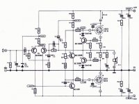
I just got the "overbright" problem with this kind of design that I attached. I modified the final stage, using ordinary discrete darlington, and not putting the output limiter. So, lets just concentrate with the differential and VAS only from the attachment.
I experimented and seems these 3 solution can work to cure the problem (widen the OLBandwith?)
1. Put Degeneration Resistor on T1, T2, T4.
2. Put resistor from collector of T4 to ground (I tried 10k)
3. Put a resistor parrarel with C6 (Parrarel to miller cap in VAS) 220K.
But I don't like the sound change with option no1 and no2. This makes me left with option no3.
In DougSelf book, putting this 220k parrarel with miller cap is a cure for "linearizing VAS". But is this also helps in widen the OLBandiwith or not?
Attachments
Hi lumanauw !
I think no1+2 simply reduce gain and widen bandwidth and linearize.
10k to ground for no2 was a bit much ? Try 47k or 100k...
I am not sure what exactly this resistor (no3) does, it should linearize
and reduce the effect of c6. Need to check. But it should also increase
bandwidth as it reduces gain.
I know what you mean with not liking the sound, i have this problem
with my last 2 amps. Optimizing them to behave "optimal" produces
unpleasant sound, it's some kind of too hard or dry. Very annoying...
So much about theory ?
Mike
Hi, Mike,
😀 Theory is good. At least it helps to understand why the amp sounds like that, and it sure helps finding the solution.
About the solution really works wonderfull or not, we should try, maybe makes variations of the solutions. We are in DIY world (with not so much measurement equipment to help)
😀 Theory is good. At least it helps to understand why the amp sounds like that, and it sure helps finding the solution.
About the solution really works wonderfull or not, we should try, maybe makes variations of the solutions. We are in DIY world (with not so much measurement equipment to help)
with 470u ,the distortion is increased by many times
 the distortion will be decreased by many times .I have just remove it .
- Status
- Not open for further replies.
- Home
- Amplifiers
- Solid State
- Symmetrical folded cascode.