MikeB: Interesting results. I've been working on a power amp project and have been experimenting with a variety of topologies. I now have two final candidates, which are quite similar in their overall approach - non-complementary JFET input with BJT cascode, a variant of a CFP (Sziklai) output stage, output equipped with zobel but no output resistor/inductor network, DC coupling, and global NFB. The power supply is a low-noise switching-mode design.
The prime topoligical differences between the candidates occurs in the sections between the input and output - one version uses a VAS with cascode, and the other uses a folded cascode (with active current sources rather than resistors). Both versions are completely stable into all loads that I have tested them with. Both are pretty good, but on the whole, I find the folded cascode preferable. The top end sounds cleaner and more pure, and everything about the sound is more solid, including spatial imaging. OTOH, I may still choose the cascoded VAS, as the results are quite acceptable, and it is simpler and appears to be somewhat more bulletproof when abused.
Maybe the choice of output stage (Darlington or Sziklai) favors one intermediate-stage topology over another.
regards, jonathan carr
jcarr said:Maybe the choice of output stage (Darlington or Sziklai) favors one intermediate-stage topology over another.
The folded cascode tends to have less gain and wider bandwidth
and thus is usually more frequency stable in feedback loops.
I am of the opinion that the Sziklai are more sensitive to stability
issues, so you can easily imagine complementary (no pun
intended) qualities. On the other hand, folded cascode works
great with output followers too, as in the X600.
Hi, Mike,
Maybe putting CCS instead of resistor in your FC will change your final result one more time 😀
Have you tried my suggestion for your FC here ?http://www.diyaudio.com/forums/showthread.php?postid=482060#post482060 Suggestion no.3and the other uses a folded cascode (with active current sources rather than resistors).
Maybe putting CCS instead of resistor in your FC will change your final result one more time 😀
yes , or I can use mr evil's topo😀OTOH, I may still choose the cascoded VAS, as the results are quite acceptable, and it is simpler and appears to be somewhat more bulletproof when abused
yes !as the cfp introduces more delay.
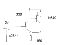
mike! this is my old vas .I have just removed it yesterday
Attachments
Hi !
My experience was, that my cascoded vas has the same quality for
top end (trebles & co), but shows the better overall sound (cleaner).
To NP:
It's only sim'd, but with similar gains the cascoded vas showed higher
OL-bandwidth and less distortions. Maybe i have wrong configuration
for my FC ?
To lumanauw:
If i remember correct, for symetrical designs the ccs didn't work good,
biasing was not defined. (Similar problem to symetric currentmirror)
To thanh:
I had not really better results with cfp in vas, seems that cfp is most
interesting for diffamps ?
I don't think that folded cascode is bad, but in my particular case it
was outperformed by the cascoded vas.
Mike
Hi Nelson:
I agree that folded cascodes are usually more stable (and require less compensation) inside feedback loops. However, it has not been my experience that this is entirely due to less OL gain.
Comparing a normal VAS vs. a folded cascode circuit - both matched for similar OL gain (around 90dB in my case), my findings are that the folded cascode requires less compensation (and a less complex compensation scheme) to stabilize.
Using the folded cascode, without any local degeneration in the input stage, and compensation applied only to the inputs of the output stage, I can apply 50-some dB of global feedback before my ears tell me that I'm overdoing things. 🙂 If I were only looking for stability on the scope, I would certainly be able to go higher. I don't recall the exact figures for the VAS version off the top of my head, but assuming a similarly simple compensation scheme, I think it would be around 8dB less global NFB before I started noticing audible artifacts.
In my experience, the appropriate phase compensation (scheme and amount) as well as amount of global NFB will be affected by the circuit structure and pcb layout, so definitely YMWV.
regards, jonathan carr
before my ears tell me that I'm overdoing things.
less global NFB before I started noticing audible artifacts.
Can you share something. What's the clue of this point? Is it audible, or we should also use help of meters.
A good designer once write that there is a "sweet spot" for an amp, that is the right OL gain with the right Feedback value. That means we cannot blindly forced to use low OL gain or high OL gain. They just need the right value with the right feedback factor, not certain low value or certain high value.
Sometimes I have problem with "not enjoyable" sound from an audio amplifier. I estimated the frequencies is about 1K,2K---5K. The high midrange region (not trebles yet).
It can be eliminated by lowering the OL gain, with the same Closed Loop gain.
I dont know what causes this "too much" midhigh. Is my modification of lowering OL gain is the right cure for this? It seems works.
Is this one of the clue for finding this "sweet spot"?
As far as compromises between bandwidth/gain and other characteristics go, I can't really offer any concrete opinions. Once distortion has been brought down to reasonabl levels, I honestly cannot be sure whether any differences I percieve are real or imagined. Measurements aren't much use either, since there it's not obvious which characteristics are to be favoured; Should distortion be lowered further, or is it beneficial to minimize phase shift at higher frequencies? My instincts say that the answer probably lies between the two extremes.
Anyway, back to output stages: Perhaps one with a low input impedance would work well. It would match better to the high output impedance of the cascode.
Anyway, back to output stages: Perhaps one with a low input impedance would work well. It would match better to the high output impedance of the cascode.
lumanauw said:
Sometimes I have problem with "not enjoyable" sound from an audio amplifier. I estimated the frequencies is about 1K,2K---5K. The high midrange region (not trebles yet).
It can be eliminated by lowering the OL gain, with the same Closed Loop gain.
I dont know what causes this "too much" midhigh. Is my modification of lowering OL gain is the right cure for this? It seems works.
Hi lumanauw !
This could mean that the cornerfreq of your ol-bandwidth was
perhaps ~3khz. So lowering the gain simply improved ol-bandwidth,
moving the cornerfreq to a level no longer audible.
The even worse thing is, you mentioned frequencies are those
most sensible to human ear...
Also possible is that you did not properly adjust feedbackcaps,
this make an amp sound too bright, as closedloopgain gets modified
by phaseshifts between input and feedback. Typically you use a small
cap (~22pF) in paralell to the voltagedivider in feedback to compensate this.
Mike
Mr Evil said:
Anyway, back to output stages: Perhaps one with a low input impedance would work well. It would match better to the high output impedance of the cascode.
Hmm, i don't understand that one...
Putting a lowinputimpedance to the highoutputimpedance seems
no a good idea to me. As inputimpedance of outputstage is reactive,
you add distortion by varying the gain/BW of the vas/FC.
That's why i prefer tripledarlington. It's always a good idea to put
some constant load to the vas (with resistors), it lowers outputimpedance,
reduces gain,increases BW and linearizes.
Mike
The idea is that the cascode, having a high output impedance, is a current source. For maximum current transfer the following stage should have a low input impedance, the same way that voltage sources should have low output impedance and feed a high input impedance. Thus gain is maximized and the required voltage swing from the cascode is reduced (ideally to nothing). The problem would be stability.
Hi, Mike,
Is that in the area of corner frequency, these frequencies will be the most obvious, like having somekind of peak? So making OL minimum of 20khz is a good thing, to advoid these kind of problem.
In practice, how far this OL gain can go? Can it reach 100khz OL?
I've tried to manipulate this midhigh with small caps in feedback, in millercap, they tend to soften the whole sound, but the peaks are still there.
Hi lumanauw !
I don't think that this peak has to do with cornerfreq. As input and
feedback at diffamp can get bigger phaseshift with higher freqs, the
actual difference between these signals increases, so closedloopgain
can increase with freq. At 60° closedloopgain has increased to
openloopgain, in theory...
You can build openloopbandwidth with 3db@100khz, but this
seems pointless to me...
I tend to adjust gain until 20khz shows smallest distortion.
I think this peak can be reduced with higher olbandwidth, but not
eliminated. Sims showed that the feedbackcap can eliminate it,
millercaps increase it... So both has to be adjusted, the bigger the
millercaps, the bigger the feedbackcap and vice versa.
But there are many possibilities giving this bright sound, one is simple
distortion, harmonics have higher freqs. Another is IMD, i heard that
it sounds bright.
I had one amp having extreme bright sound, i was able to get rid of it
by adding many caps, but i discarded this amp.
About this cornerfreq, i need to do some more research...
It's too theoretical to make statements, but i have the feeling that
this issue is underestimated.
Mike
Good point, Mike,
At RTA, the curve is always flat. There is no magnitude peaking.
But the sound is like having too much response at 1k-5khz.
Maybe what you said is right. Phase Shifts. With flat magnitude response, but if the phase differs in those frequencies, they would be heard like peaking?
Or is it the AM FM PM distortion that being discussed at the other thread?
Audio is complex. It expands away from just looking at a good schematic. 😀. Never tought have to deal with these complex "mathematical-related" issues. But right now it is a must know, or we cannot make good sounding amp.
So measuring the bandwidth does not show any peak ?
But still the sound is bright ? Might be IMD.
This might be some sort of these AM/FM/PM.
My point is, that a sinewave says not much about the quality of an amp...
But it seems that high OL-bandwidth with "low" thd seems a good thing.
The sound of these phaseshifts is the thing i need to research, i want
to try to simulate these dynamic phaseshifts with an algorithm and
apply these to a wavefile. I can do this with a FFT, ensuring that no
thd is generated. If sound changes, it prooves that a thd of 0.0%
is completely worthless.
Mike
Hi, Mike,
The peaking range is not exactly in trebles, but lower than trebles, but higher than midrange. It is fatiguing, it makes me wanted to turn off the volume instead of raising the volume. With other amp that do not suffer this, I just wanted to raise the volume to enjoy the music.
The frequency response is roughly measured, with AudioControl RTA, which only has 31band and +/-3db step. The frequency response is flat, but the other amp that do not have this is also flat.
So If there is no magnitude peaking, it has to be Phase Shift thing, if the Frequency Responses are the same.
Mike, since you are good with math and programming, if you have time, could you search if a certain bandwith within 20-20khz (like 1khz-5khz) if phase shifted, it will audible like it has peak? (Even if all the magnitudes are the same) And how far this phase shift makes you want to turnoff the amp?
I suspect if there is a bandwith (if phase shifted) makes you want to turn off the amp, possibly there are other bandwith(s) that if phase shifted you wont notice it, or even gives pleasure sound (just like you experimented with 2nd and 3rd harmonic and "puke" effect).
If you have know this, it will be your "hidden knowledge" that other designer dont have in making good sounding amp😀
Knowing what is this phase shift, what's their effect and what's the cure in practical amp will make ability to make good sounding amp. Combined with the ability to make good measuring one, it would be perfect, wouldn't it? Very low THD with good sounding.
We know distortion as a single word "THD" but we forgot that there are 2 dimensions that makes THD. One is Magnitude distortion, the other is Phase Shift distortion. It developes to AM FM PM (that I dont understand clearly) in other thread. We dont talk much about phase shift region in this DIY comunity, maybe because the measurement device is soooo expensive.
But at least we start to recognize it with it's very obvious effect on sound reproduction (while not easy to measure or even to look at this phase shift(s).
😀 I see only green color on the osciloscope, if there is a music playing. How can I see if the output is shifted?
The peaking range is not exactly in trebles, but lower than trebles, but higher than midrange. It is fatiguing, it makes me wanted to turn off the volume instead of raising the volume. With other amp that do not suffer this, I just wanted to raise the volume to enjoy the music.
The frequency response is roughly measured, with AudioControl RTA, which only has 31band and +/-3db step. The frequency response is flat, but the other amp that do not have this is also flat.
So If there is no magnitude peaking, it has to be Phase Shift thing, if the Frequency Responses are the same.
The sound of these phaseshifts is the thing i need to research, i want to try to simulate these dynamic phaseshifts with an algorithm and apply these to a wavefile. I can do this with a FFT, ensuring that no thd is generated. If sound changes, it prooves that a thd of 0.0% is completely worthless
Mike, since you are good with math and programming, if you have time, could you search if a certain bandwith within 20-20khz (like 1khz-5khz) if phase shifted, it will audible like it has peak? (Even if all the magnitudes are the same) And how far this phase shift makes you want to turnoff the amp?
I suspect if there is a bandwith (if phase shifted) makes you want to turn off the amp, possibly there are other bandwith(s) that if phase shifted you wont notice it, or even gives pleasure sound (just like you experimented with 2nd and 3rd harmonic and "puke" effect).
If you have know this, it will be your "hidden knowledge" that other designer dont have in making good sounding amp😀
Knowing what is this phase shift, what's their effect and what's the cure in practical amp will make ability to make good sounding amp. Combined with the ability to make good measuring one, it would be perfect, wouldn't it? Very low THD with good sounding.
We know distortion as a single word "THD" but we forgot that there are 2 dimensions that makes THD. One is Magnitude distortion, the other is Phase Shift distortion. It developes to AM FM PM (that I dont understand clearly) in other thread. We dont talk much about phase shift region in this DIY comunity, maybe because the measurement device is soooo expensive.
But at least we start to recognize it with it's very obvious effect on sound reproduction (while not easy to measure or even to look at this phase shift(s).
😀 I see only green color on the osciloscope, if there is a music playing. How can I see if the output is shifted?
Some years ago I took part in listening experiments that were designed to check the relationship of phase shift to multi-tone masking thresholds. I don't recall the details, but I was left with the very clear impression that phase shifts that were inaudible on their own _would_ alter masking thresholds.
It reminded me a little of subsonic frequencies - we may not be able to hear a 10Hz tone by itself, but when that 10-Hz tone modulates the amplitude or frequency of another tone, you will be able to hear the results.
regards, jonathan carr
It reminded me a little of subsonic frequencies - we may not be able to hear a 10Hz tone by itself, but when that 10-Hz tone modulates the amplitude or frequency of another tone, you will be able to hear the results.
regards, jonathan carr
Well, at least these phaseshifts have not big effect and it seems they
don't produce this bright sound...
Some experiments with algorithms showed that it seems unstability
causing this. And increasing OL-bandwidth simply enables the feedback
compensating/suppressing these audible artifacts ?
Mike
don't produce this bright sound...
Some experiments with algorithms showed that it seems unstability
causing this. And increasing OL-bandwidth simply enables the feedback
compensating/suppressing these audible artifacts ?
Mike
- Status
- Not open for further replies.
- Home
- Amplifiers
- Solid State
- Symmetrical folded cascode.