A current mirror with two dies generates just as much noise. Didn't he mean any current mirror, single die or multiple die, without emitter degeneration?
I'll try to dig it up from my library and post you a pm of the scan.
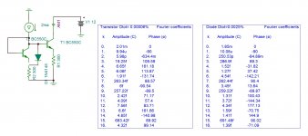
You are right , with identical transistor wired as diode the current mirror is near perfect . The problem is that to bias the outputs, the mirror must reflect a dc current less than it receives by 90uA to bias the output transistors . The reflected dc current with transistor ,as you read on the measurement 2.01mA, is 10uA more . With diode as you read is 1.85mA, 150uA less , by this I can adjust it to 90uA either by reducing the emitter resistor or increasing the base current of the mirror .D1-T7 and D3-T9 in post #30 don't match, as a 1N4148 is not a BC550C or BC560C (although the much increased emitter resistors and tail currents should make the circuit less sensitive to that).
Attachments
Last edited:
I made an error . The supply voltage on precedent test circuit should be 1.2V instead of 12V. Then the currents are 1.99mA and 1.82mA .
Assuming that that 90 uA has to be accurate to within +/- 50 %, you can allow an error of 45 uA. You have differential pairs biased at 4 mA tail current with current mirrors. A mismatch of 600 uV between the VBEs of the differential pairs already gives you a 45 uA offset, if I calculated it correctly.
You will need very well matched transistors and accurate current mirror emitter resistors to have any chance to get this working, unless you come up with some clever self-calibrating loop.
You will need very well matched transistors and accurate current mirror emitter resistors to have any chance to get this working, unless you come up with some clever self-calibrating loop.
You are forgetting that the bias current is adjustable by R10. If due to mismatch you have less than 90uA without any R10 applied than the bias can be adjusted in double transistor current mirror case ,or else the transistors in the differential must be swept if they are unmatched . In diode current mirror, R10 decreases the unbalance. If the differentials unbalance less than 90uA ,Than R10 can still decrease it. To remind that the feedback balances upper and lower unbalance.
The four differentials must be matched 2 pairs . Matching is done by measuring with a universal multi meter ,on diode position, the diode voltage of (B+C)-E , without touching by fingers. The lower the value higher is the gain. Normally from 5 pieces I get a matched pair . To get 2 pairs of matched pairs statistically 25 pieces are needed , A dozen of each type . The same for current mirrors. The outputs need a 12v along an amp meter on the collector , the transistor mounted on a small heat sink a base current applied by a 1M ohm adjust to get 15mA . A pair that has about the same adjust ohms is chosen.
The four differentials must be matched 2 pairs . Matching is done by measuring with a universal multi meter ,on diode position, the diode voltage of (B+C)-E , without touching by fingers. The lower the value higher is the gain. Normally from 5 pieces I get a matched pair . To get 2 pairs of matched pairs statistically 25 pieces are needed , A dozen of each type . The same for current mirrors. The outputs need a 12v along an amp meter on the collector , the transistor mounted on a small heat sink a base current applied by a 1M ohm adjust to get 15mA . A pair that has about the same adjust ohms is chosen.
Last edited:
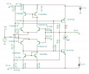
Now the circuit (post 44) make sense to me. Endstage bias is set with R10 (mainly) to be modulated by the difference of current output of first stage differentials and current mirrors.
Without this bias fixing R10 the amp is totally dependent of this minute current difference from the first stage, hopefully completely temperature stable.
I wouldn't bet on such an extreme fluid design. Might work in class A in summer, to become B in winter. BJT's are nasty with temperature. Can you perform a temp-sweep simulation with your software? Let it run from -20ºC to +60ºC and bias current as output.
When it comes to ultra stable minimum component count designs, I'll switch to Hiraga (6 BJT's, 10 R's, 2 C's and a pot, 19 in total).
The output transistors work with unique type of bias , current instead of voltage ,this is the ingenuity of Günter's circuit . The bias normally depends on Ic/Vbe diode transfer function , here it is Ic/Ib that is Hfe dc curve that gives the bias . The temperature variation not only effects very little , but also the value of the bias itself is not very critical . The Hfe curves show it double or halves by +/-75°C. That is 15ma can become 7.5/30 ma . This is ambient temperature of -50°C to 100°C .
The only amp I know that is current biased is the JLH class A amp . Do you know another one?
The only amp I know that is current biased is the JLH class A amp . Do you know another one?
Last edited:
None, frankly.
Current biased amps appears to be a bit exotic after all, considering above discusions.
Keep in mind that Ic-Ib char's are very nonlinear and are temp- and current-dependent none the less. Counts two wacky variables in obtaining a stable topology.
Thus no bets from me. Eager to view a temp-plot though.
In my signature below, on the right side, one can determine that temperature-stability is an intrinsic component of the dc-stability of any such applied circuit with semi's, by the single nature of bjt's alone. Written with a capital T.
Last edited:
The IC-VBE characteristic of a bipolar transistor is very nonlinear (ideally exponential, current increases by a factor of e for each kT/q increase of VBE), compared to that the IC-IB characteristic is almost straight - although in this case we have Darlington transistors with internal resistors that may mess things up a bit at low collector currents.
Trimming the bias current will help a lot, but you have to be careful with temperature gradients or unequal dissipation. That 0.6 mV allowable differential pair offset I calculated corresponds to 0.3 K of temperature difference between the differential pair transistors.
Ian Hegglun has published some amplifiers with current-driven output stages, if I remember well. My MOSFET amplifier from the mid-1990's also has current-driven output devices.
Gunterflunder's circuit has the current mirror output transistors biased in saturation, so it is not really pure current drive. In fact that's what causes its non-switching behaviour, I expect that kokoriantz's circuit switches off the NPN side when the PNP side conducts large currents and vice versa.
My MOSFET amplifier from the mid-1990's also has current-driven output devices.
That is, they are current driven, but obviously not biased by just forcing a certain gate current and seeing what happens.
Even if all active components in such a sensitive design were mounted on an infinite heatsink, transition through the Ic-Vbe curve during processing / modulation (inputsignal) causes the curves to differ in the input differentials, the current mirrors and the output stage.
On die-level, these differences will contribute 'thermal distortion' (as this was not present in the input signal) which has to be corrected by the feedback loop. Increasing the loopgain to cope with this makes the design even more sensetive to these errors.
As long as there is a serious temperature component in the active parts transition equation, one has to deal with it during the designing process to converge into a reliable amplifier which can be build even on diy-level.
Hi MarcelvdG,...Ian Hegglun has published some amplifiers with current-driven output stages, if I remember well. ....
Thanks for mentioning that. I have just posted a snippet of that article on another thread here Class AB+C: Anybody tried it? Is it worth it? and circuit here Class AB+C: Anybody tried it? Is it worth it?
A variant is here IansAmpShowcase – Google Drive
It's a Differential Rush Diamond IPS, with current drive power stage, with Miller neutralization (like 1970's AM radio IFT stages) which pretty much solves the cross-conduction issue and can run happily at 100kHz with full swing. My best offering to date and fee for anyone to use for hobby and commercially.
While on Diamond variants this one uses trench FET's to give a FET character to bipolar power transistors IansAmpShowcase – Google Drive. It is a variation of my Sep 1995 EW Squarelaw circuit here. Notice it does not need complementary FET's!
@gunterflunder, I hope some of my ideas will help your research.
Cheers,...
Fixed links
Oops, seems my Gdrive links got mixed up. Try the following links:
A variant is here CSD with Miller Neutralization
It's a Differential Rush Diamond IPS, with current drive power stage, with Miller neutralization (like 1970's AM radio IFT stages) which pretty much solves the cross-conduction issue and can run happily at 100kHz with full swing. My best offering to date and fee for anyone to use for hobby and commercially.
While on Diamond variants this one uses trench FET's to give a FET character to bipolar power transistors The Echo Amp -- Adventures in Rush Wonderland. It is a variation of my Sep 1995 EW Squarelaw circuit here. Notice it does not need complementary FET's!
- Status
- Not open for further replies.
- Home
- Amplifiers
- Solid State
- symmetric audio amplifier