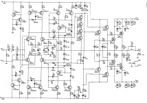
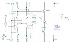
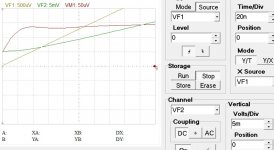
I made a simple model without current mirrors to start with . Biased 150ma with 0 ohm input source impedance 8 ohms load to expect 25 decent watts . The first results are spectacular. Dtot=0.14% at 5w to 20w 1% at 25w . The blindness is 50ns too high to reproduce the most difficult requiem of Mozart (20ns) but sufficient to reproduce the pleasant beat of horns in large jazz orchestras, as sing sing sing of B. Goodman's. Very promising. Thermal stability is a difficult issue here.
It sounds promissing. The amp is dedicated to produce 10..12 W rms-Power at a 4 Ohm load (Magnat Vector 1). Therefore I have chosen to operate it at +/- 12 V to ground. For thermal stability I would like to mount the diode pairs at the heat sinks of the transtistors for the output stage.
To your schematic: what is the inductance for? Is it dedicated to substitute the Zobel circuit in my circuit? What are the advantages?
Last edited:
Your circuit is current biased . The error current of the mirror due to base currents flows to the outputs, independent of the collector-collector potential. It is ok if you can master the hfe of the mirrors and the outputs . If one is different than you bias eider class C or A not talking about offset. Before I start reinventing the wheel I am looking what has been done , as Stochino's amp for example. Once I adjust in 8 ohms/ 25w (easier)then I lower the output impedance for 4 ohms .
The inductance if set to 1G the amp becomes ac open loop to investigate it's behavior.
The inductance if set to 1G the amp becomes ac open loop to investigate it's behavior.
Attachments
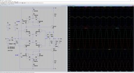
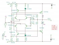
R11 and R17 adjust bias of each output hence the offset . The mirrors more than doubled the open loop gain . The distortion at 5w now is 0.06% and the blindness reduced to 30ns . This is a very high quality amp and I didn't yet fin adjusted, it is a quick trial . Bias is 123ma .
Attachments

With the Stochino circuit, the collector-collector node is fixed with the cm-diodes (other than the initial circuit). In the adjusted circuit these are D1--4. Now it works for audio.
What's the purpose of T11/T12/D5/D6-leg?In the Stochino this is a second cm stage.
Because you use an inverted totempole (C-C output instead of E-E output), there is no need for this leg. R18 is a global warmer only.
What's the purpose of T11/T12/D5/D6-leg?In the Stochino this is a second cm stage.
Because you use an inverted totempole (C-C output instead of E-E output), there is no need for this leg. R18 is a global warmer only.
R11 and R17 adjust bias of each output hence the offset . The mirrors more than doubled the open loop gain . The distortion at 5w now is 0.06% and the blindness reduced to 30ns . This is a very high quality amp and I didn't yet fin adjusted, it is a quick trial . Bias is 123ma .
I did some further tuning for thermal stability. Therefore I have reduced the matching resistors in the differential amplifier stage to 10 Ohm and increased the emitter resistors of the output stage. The quiescent current at room temperature is now about 30 mA, at a temperature of 150 °C it will rise up to 70 mA. It is no more necessary to couple the diodes with the output stage heat sinks. This is just fine.
The aim is to live with a very low number of transistors. Therefore the output stage ist not only a current amplifier but a voltage amplifier as well. In this way I can save another voltage amplifier stage after the differential amplifier stage. Another aim is to make a circuit, where it is not necessary to adjust something.
kokoriantz, I have realized that your feedback network has a very low impedance. What is the purpose for this?
Attachments
Last edited:
Without R18 global warmer the bias falls to 102ua . The transistor + diode + resistor works as VBE . I will replace them by more conventional ones .
Indeed biasing with current you don't go thermal runaway as the hfe thermal variation is positive but a ratio less then unity . For this you don't need 0.22 ohm on emitters as their voltages don't feedback the base currents, ac or dc . Sometimes to go from point A to B you need to pass through Z . You must keep in mind that this is two independent error amplifiers to be correcting a single feedback.
Low impedance feedback reduces the effect of the input capacitance , hence faster feedback, higher frequency response . Adding a zero to the feedback resistors the frequency response gets reduced to 400khz (who cares) and the blindness is 100ns .
Last edited:
R11 and R17 adjust bias of each output hence the offset . The mirrors more than doubled the open loop gain . The distortion at 5w now is 0.06% and the blindness reduced to 30ns . This is a very high quality amp and I didn't yet fin adjusted, it is a quick trial . Bias is 123ma .
I have found on Mouser matched dual pnp / dual npn arrays THAT340P. So the matching resistors are no more necessary. This simplifys the circuit and the pcb a lot. R3, R4, R7 and R8 need to be set to 0.5 Ohm.
Attachments
Last edited:
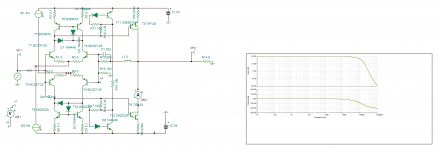
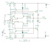
This is current biased version . As the biasing current is due to mismatch of current mirrors so why not adjust the mismatch by resistors . These 6.8k resistors can be composed of R+ PTC to follow thermally. The dynamic characteristic is similar for 4 ohms . It can deliver 50w with 0.3% dtot . The output impedance is 0.01 ohms up to 100khz see curve. I see back tomorrow.
Attachments

Last edited:
I have found on Mouser matched dual pnp / dual npn arrays THAT340P. So the matching resistors are no more necessary. This simplifys the circuit and the pcb a lot. R3, R4, R7 and R8 need to be set to 0.5 Ohm.
Noisevectors on same die are mostly evenpointed, contributing in overal noise.
Hence discretes in low noise circuits. Noisespec of the T~340 is 0.75/0.8 nV/sqrtHz: ok.
Arguments about baseconnection of TIPs:
Y/Yo=(e)exp(X/Xo){Xo=kT/q}
where Y=Ic, Yo=Icob, X=Vbe
Ve is close to powerrail, Vb is depending on static characteristics of highZ collectors with Early effect.
Hoe of T~340 is not specified or easy to figure out. No graphs either.
Further reading:
BJT h-Parameters and Amplifier Characteristics Lab
http://ux.brookdalecc.edu/fac/engtech/andy/engi242/bjt_models.pdf
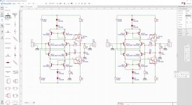
This configuration gives better bias control, the emitter resistors can be paralleled by NTC glued with silicon glue upon the transistors if constant bias is desired. The bias gives best results at 15ma only , as the outputs heat up 75°C increase junction temperature ,the bias will double to 30ma . For this the smallest heat sink should not be more then 28°C/W to avoid runaway. If the heat sink is oversized , lets say max increment of 25°C ,no thermal compensation will be necessary. Tell me if this configuration suits you so I start designing the CCS only with passive components using bootstrap technique.
Attachments
THAT3*0 transistors have lower hfe, but the 'emitter degeneration' is built in so no emitter resistor is required. They are actually separate dies, matched, and placed into the same package. In my experience, very good devices.
TIP120/125 are lower Gm Darlington, TIP100/105 might be better for driving speaker,
TIP120/125 are lower Gm Darlington, TIP100/105 might be better for driving speaker,
Last edited:
This configuration gives better bias control, the emitter resistors can be paralleled by NTC glued with silicon glue upon the transistors if constant bias is desired. The bias gives best results at 15ma only , as the outputs heat up 75°C increase junction temperature ,the bias will double to 30ma . For this the smallest heat sink should not be more then 28°C/W to avoid runaway. If the heat sink is oversized , lets say max increment of 25°C ,no thermal compensation will be necessary. Tell me if this configuration suits you so I start designing the CCS only with passive components using bootstrap technique.
Why do you put devices that don't match in the current mirrors?
Noisevectors on same die are mostly evenpointed, contributing in overal noise.
Hence discretes in low noise circuits. Noisespec of the T~340 is 0.75/0.8 nV/sqrtHz: ok.
If you mean that noise between devices on the same die is largely correlated, I disagree; matching devices on the same die still generate noise independently. Not that it matters much anyway in this case.
which devices ?Why do you put devices that don't match in the current mirrors?
If you mean that noise between devices on the same die is largely correlated, I disagree; matching devices on the same die still generate noise independently. Not that it matters much anyway in this case.
I was referring to professor Nordholt's publication 'Noise' (Delft, ~ '90's) where he reports his findings about same die current mirrors: "... these current mirrors are noise generators...".
This design looks promissing, kokoriantz. Just a few questions:
- Is it necessary to use matched BC327 / BC337 for the differential amplifier? Why don't you use the BC547 / BC557? Why do you use different transistors in the current mirrors?
- About your modification of the current mirrors. The diode and the BE-Diode of the transistor set the voltage for the bases of the output transistors. The resistors set overvoltage for the bias current through the output stage. Why do you use 290 / 300 Ohm? Isn't it possible to set both to 300 Ohm? Or is it necessary to adjust the bias current by use of R1 and R3?
- Why do you use 4 mA current sources? I have used 1 mA in order to apply the E-103 current regulator diodes of Semitec. I can also use the E-452 which gives me 4.5 mA. Higher CE-currents of the input stage can probably compromize the input impedance.
Last edited:
The bc327/337 transistors have lower emitter resistors hence higher IC/Vbe transconductance than other transistors . The emitter resistance is inversely proportional to IC . As I need highest gain to get low output impedance and high NFB for low distortion , I pushed it to 2ma bias /transistor. My simulator doesn't have 327 -40 model so I use 25 version.
The bias technique you chose is based upon the mismatch or unbalanced current mirrors . If the mirror reflects exactly the opposite current so no any biasing dc current can flow to the bases of the outputs , then the precedent solutions is to consider. I replaced the mirrors with bc327/328 , the distortion rose a little bit and as it's hfe being lower I had to pull harder .
The passive CCSs work very fine . If unregulated supply is used , zeners should be added .
I am trying to make the bias adjusted by a single resistor .
Attachments
I was referring to professor Nordholt's publication 'Noise' (Delft, ~ '90's) where he reports his findings about same die current mirrors: "... these current mirrors are noise generators...".
A current mirror with two dies generates just as much noise. Didn't he mean any current mirror, single die or multiple die, without emitter degeneration?
which devices ?
D1-T7 and D3-T9 in post #30 don't match, as a 1N4148 is not a BC550C or BC560C (although the much increased emitter resistors and tail currents should make the circuit less sensitive to that).
Last edited:
- Status
- Not open for further replies.
- Home
- Amplifiers
- Solid State
- symmetric audio amplifier