I,ve helped built 8 of these pcbs not one hummed or went crazy,,even with junk box parts. Evette
I,ve helped built 8 of these pcbs not one hummed or went crazy,,even with junk box parts. Evette
I actually never asked... What is the approx Output power of that amp in 4 ohms fed with 42Vdc rails?
Ciao!
Do
about grounding....
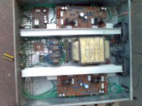
it is said, to prevent ground loop, star gnd. of pcb should be connected to chassis or HQG. in an absolute zero resistance.But it is impossible to have a zero resistance.One way of minimising the resistance is to use a thick wire from star gnd.(pcb) to chassis.
the second method I have used is that I have used a double sided pcb and all the gnd wires(input,decoupling,speaker gnd and etc.)are SOLDERED onto it. and pcb was bolted into chassis with eyelet between the screw and pcb.and placed it near the amplifier board reducing the lenght of wires.
Screwing the connectors and stacking it into one screw creates more resistance. it is said that current takes the least resistance.
here is photo that I have used in optimos.
regards,
joel
Hi, evette, nice to know that board are working fine. thanks.😉
Attachments
Whats new ? Whats happening ? Is everyone enjoying the best sounding amplifier this side of the galaxy, tell us about it.
Hi all, there are new territories to conquer
http://www.diyaudio.com/forums/club...nnual-vancouver-island-diyfest-2012-a-10.html
Schedule 2012 : 5th Annual Burning Amp Festival ? October 28, 2012
Is your SYMEF ready
http://www.diyaudio.com/forums/club...nnual-vancouver-island-diyfest-2012-a-10.html
Schedule 2012 : 5th Annual Burning Amp Festival ? October 28, 2012
Is your SYMEF ready
I hate to say that not much has happened. The SYMEFs are done, but I'm still waiting for the transformers. 😡
I have some nice heatsinks at work that I plan on using.
Itching to try them out!
Since I don't have any transformers yet (and I know that you are looking forward to hearing from US as soon as possible) I won't jump on the DIFFQC yet. However, I am looking forward to building it when I'm done with the SYMEFS.
Harrison, please, how about using 35+35V as supply voltage?
A small decay in output power won't be any trouble for me.
But, will the circuit behave well?
Thank you.
Max.
A small decay in output power won't be any trouble for me.
But, will the circuit behave well?
Thank you.
Max.
Harrison, please, how about using 35+35V as supply voltage?
A small decay in output power won't be any trouble for me.
But, will the circuit behave well?
Thank you.
Max.
Please do 😀
I hate to say that not much has happened. The SYMEFs are done, but I'm still waiting for the transformers. 😡
I have some nice heatsinks at work that I plan on using.
Itching to try them out!
Since I don't have any transformers yet (and I know that you are looking forward to hearing from US as soon as possible) I won't jump on the DIFFQC yet. However, I am looking forward to building it when I'm done with the SYMEFS.
Will start soldering today 🙂
Looking forward

Update: transformers left Poland yesterday 🙂 that means that I will have them by the end of this week (fingers crossed) I am really excited.
Update: transformers left Poland yesterday 🙂 that means that I will have them by the end of this week (fingers crossed) I am really excited.
Not much - but the building has started 😛
Very nice. Guess whos more excited and nail biting. Its like that first date,
 . Will it be love at the first tone ?
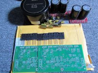
Hi guys, I started to gather the parts but I guess it will not be built as I will be moving houses again. As you see I have the PCB's with power transistors MJL3281 and MJL1302. Also Nichicon FW 47 and 100 µF caps are included and a nice shielded toroid and 2 power supply PCB's with 2 x 10.000 uF 63 V Nichicon KG each. If anyone wants this set please send me a PM. Considering the weight of the toroid shipping within Europe would be better. I am in a hurry right now but I think 120 Euro would be a fair price.
Sorry Harrison, but better an amp that will be built than an unfinished amp in a closet.
Sorry Harrison, but better an amp that will be built than an unfinished amp in a closet.
Attachments
Quick question:
Is it only the biggest 4 transistors that need to be connected to a heatsink?
Sincerely
Is it only the biggest 4 transistors that need to be connected to a heatsink?
Sincerely
Quick question: (sorry about the double post. cannot delete the former)
Is it only the biggest 4 transistors that need to be connected to a heatsink?
Sincerely
Still missing: 1 power transistor (in transit)
mur120 diodes
some fuses
22nf caps
coil? (Is it necessary)
4.7uf caps... (forgot to order...) - will try to find some things in the closet.
Is it only the biggest 4 transistors that need to be connected to a heatsink?
Sincerely
Still missing: 1 power transistor (in transit)
mur120 diodes
some fuses
22nf caps
coil? (Is it necessary)
4.7uf caps... (forgot to order...) - will try to find some things in the closet.
Attachments

More questions 😀
I guess C8 and C9 together corresponds to C7 according to the schematic here:
http://www.harrisonaudiolabs.com/Amplifiers/SYMEF/SYMEF.pdf
How important is the values here? (4.7uf) (and what is the purpose?) Could it be reduced or raised?
It is directly in series with the incoming signal and should therefore be of best possible quality?..
And: R21 =100ohm.. At the incoming signal. Is this value also extremely important or since I have some great resistors of 150ohm.. Could I use those?
Sincerely
More questions 😀
I guess C8 and C9 together corresponds to C7 according to the schematic here:
http://www.harrisonaudiolabs.com/Amplifiers/SYMEF/SYMEF.pdf
How important is the values here? (4.7uf) (and what is the purpose?) Could it be reduced or raised?
It is directly in series with the incoming signal and should therefore be of best possible quality?..
Sincerely
'tis a coupling cap to block off DC. Best quality in that position is always better but Wima and Panas are great. You can go with boutique stiff as well (Auricap, etc...)
Do
Thanks alot. How about value of it... I don´t want any bass rolloff 🙂 How large(or small) should/could it be?
BTW: My preamp is transformer coupled and therefore quite immune to letting DC out.
BTW: My preamp is transformer coupled and therefore quite immune to letting DC out.
Last edited:
Thanks alot. How about value of it... I don´t want any bass rolloff 🙂 How large(or small) should/could it be?
BTW: My preamp is transformer coupled and therefore quite immune to letting DC out.
I believe 2.2 - 4.7uF is ok but maybe wait for Harrison's answer on this one. Try to avoid electrolytics in that position...
If your preamp is transformer coupled on the output then there should not be any DC issue. You might even be able to get rid of the coupling cap.
I have some LM3886 amps that had coupling caps and I got rid of them by using Lundahl LL1545A on the input. Sounds much better but then again, you can go for top quality caps and get really good results as well.
Just wait for Harrison
Do
- Home
- Amplifiers
- Solid State
- SYMEF amplifier