
In order to achieve the goal of 30,000 reviews for the data analysis, we need more of you sharing with us your experinces. You may build your own PCB or you could show interest here 😀 http://www.diyaudio.com/forums/group-buys/217240-symef-2nd-generation-pcb-group-thing.html
More progress of my SYMEF
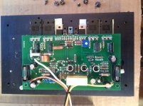
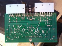
Got some free time during this weekend, so resumed my build again. The difficult part is drilling, tapping and finally aligning the transistors and bending them carefully so they are same height.
I've spent several hours on this. While tightening screw on one of the power transistor the screw head came off. Made a failed attempt to remove the leftover part, don't have patience to drill new set of holes. Luckily I had a L shaped object that I've used to keep the other transistor in contact with the heatsink.
Fired up and measured all the voltages, they seems fine and the offset is only 2mv. Need to setup the bias, what is the recommended value of the output current for these transistors? May be I'll test with real speakers next week.
Attachments

Much of the same happened to me. One screw head fell off. But I think I managed to make it work. Out travelling now. Will look into the Symef build again tomorrow.
Got some free time during this weekend, so resumed my build again. The difficult part is drilling, tapping and finally aligning the transistors and bending them carefully so they are same height.
I've spent several hours on this. While tightening screw on one of the power transistor the screw head came off. Made a failed attempt to remove the leftover part, don't have patience to drill new set of holes. Luckily I had a L shaped object that I've used to keep the other transistor in contact with the heatsink.
Fired up and measured all the voltages, they seems fine and the offset is only 2mv. Need to setup the bias, what is the recommended value of the output current for these transistors? May be I'll test with real speakers next week.
Very nice.🙂 Try keep the output wire away from the input. Ensure that the transistor where the screw head came off has enough contact with the heat sink.Its failure could lead to a cascade. Set bias by having 23mV across R14. Cheers.

1. Hi, kindly report your findings. I appreciate all the good work you do 
2. Those in need of PCBS lets meet here http://www.diyaudio.com/forums/group-buys/217240-symef-2nd-generation-pcb-group-thing.html (we need 9 more people)🙂
2. Those in need of PCBS lets meet here http://www.diyaudio.com/forums/group-buys/217240-symef-2nd-generation-pcb-group-thing.html (we need 9 more people)🙂
Thank you Mr. Harrison, I've set the bias as you suggested. Amplifier build is finally complete over this weekend, ofcourse need a very good case to justify its performance. There is no hint of any oscillation, bias is quite stable, and vbe multiplier is quite responsive to heatsink temperature. Probably need to adjust the bias after it reached steady state.
Measured 1khz and 10khz square wave and 10khz sinewave response, its clean and rounded edges on square waves.
Played through my home made bookshelf speakers. In one word, the sound is marvelous. Although I have to do an extensive listening the amp just displays its character in the first song itself. Sound stage is huge, vocals are accurate and highs are detailed. Overall the sound is very balanced in the whole audio range, no slamming bass or shrill voice. Its just perfect, you don't want to stop listening.
I am not comparing this amp in isolation. I've already built SymAsym, and F5 also I have couple Luxman amps, so I have some very good amps for reference. Being said that, this is a very good sounding amp with huge soundstage and openness.
Hello Mr. Harrison, I don't know what is your magic formula is, but it is wonderful. I cannot stop listening to this amp. To justify its sound, I'll get a very nice case with bigger heatsink and route the wires cleanly.
Bambadoo, what are you waiting on? Complete the amp you'll be greatly rewarded.
Attachments

Thank you Routhun, for taking the risk, the time, the investment to checkout this amplifier.  It also provides great pleasure when it pays off.🙂 Thank you for contributing to the state of the art.
It also provides great pleasure when it pays off.🙂 Thank you for contributing to the state of the art.Hi Routhan,
kindly would you take a measurement of a 100 Hz and 20 Hz square waves, this may give some indication of the low frequency response.
kindly would you take a measurement of a 100 Hz and 20 Hz square waves, this may give some indication of the low frequency response.
Hello Mr. Nico,
I couldn't take the measurements tonight, I'll capture them in a day or 2 and post here.
Thanks,
Routhun
I couldn't take the measurements tonight, I'll capture them in a day or 2 and post here.
Thanks,
Routhun
Join us for an exciting adventure. 😀 Put your ears to the test.(Your feedback is really needed) Tell us all about it and advance the state of the art.🙂 Join us for round 2. http://www.diyaudio.com/forums/group-buys/217240-symef-2nd-generation-pcb-group-thing.html
Hi Harrison/Routhun,
the test I am proposing is not to show up anything bad in the amplifier, I would not do that. What I am suspecting is that the low frequency strain on the power supply would be exactly what is being discussed in the reservoir capacitor thread and what looks like 20 000uF/rail on the photo.
The only reason I asked for the test is that it seemed that routhun was already set-up to do another test. If you have already closed up routhun then do not bother, we will catch someone else who may be about to test an amp.
Hello Mr. Nico,
I couldn't take the measurements tonight, I'll capture them in a day or 2 and post here.
Thanks,
Routhun
Hi Routhun, if the square wave test shows bad results do not try and solve it, just show us. I am very keen to see how the reservoir caps rail hold up in a real test. Remember that the test must be into a load else the test is useless.
Hi Nico,
Power supply reservoir capacitors are 18000uf,50v panasonics. The total capacitance in this amp is 72000uf for both the channels. I am measuring the waveforms with 8 ohms pure resistive load connected to the output. Any case I'll measure and upload the results soon.
Thanks,
Power supply reservoir capacitors are 18000uf,50v panasonics. The total capacitance in this amp is 72000uf for both the channels. I am measuring the waveforms with 8 ohms pure resistive load connected to the output. Any case I'll measure and upload the results soon.
Thanks,
Hi Routhun,Hi Nico,
Power supply reservoir capacitors are 18000uf,50v panasonics. The total capacitance in this amp is 72000uf for both the channels. I am measuring the waveforms with 8 ohms pure resistive load connected to the output. Any case I'll measure and upload the results soon.
Thanks,
It will definitely be interesting to see the output waveform with so much capacitance per rail.
Would maybe support Gootee's forecast that under power supply stress conditions there may not be enough time to recharge the capacitors. Besides it would be of as much interest to your fellow SYMEF constructors. Thanks for participating Routhun.
Sorry for highjacking your thread Harrison.
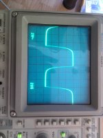
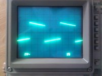
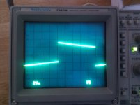
SYMEF measurements
Hi Nico,
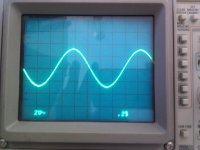
Here is the square response of SYMEF at 20hz, 100hz, 10khz and 20khz into 8ohms pure resistive load.
Thanks
Hi Nico,
Here is the square response of SYMEF at 20hz, 100hz, 10khz and 20khz into 8ohms pure resistive load.
Thanks
Attachments

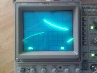
Thank you very much Routhun. I trust that you found this low frequency response both unexpected and puzzling. However, your scope is on AC coupled please use DC coupled else the effect is accentuated by the probes high pass filter. I would like to see your power supply's effect on the low frequency.
Last edited:
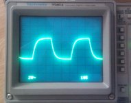
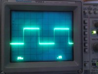
SYMEF measurements with DC mode
Hi Nico,
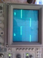
Thank you for correcting me it was my mistake, I was using the AC input mode thats why square wave response is not great at lower frequencies. Now I measured again with DC input mode, now the response looks much better.
Thanks,
Hi Nico,
Thank you for correcting me it was my mistake, I was using the AC input mode thats why square wave response is not great at lower frequencies. Now I measured again with DC input mode, now the response looks much better.
Thanks,
Attachments

- Home
- Amplifiers
- Solid State
- SYMEF amplifier