The NFB capacitor should never have any voltage across it.
When the amp is properly assembled that resultant non voltage will result in an inaudible capacitor.
One should never need to "help" (bypass) an electrolytic for normal Audio band signals.
When the amp is properly assembled that resultant non voltage will result in an inaudible capacitor.
One should never need to "help" (bypass) an electrolytic for normal Audio band signals.
At VHF the input filter reduces the signal to an almost insignificant amount.
In the audio band where the input filters allow the full electric signal to pass through there should be no significant voltage across the NFB DC blocking cap.
Electrolytic ESL and ESR should still be low enough that in the octave or two above the conventional 20kHz assumed upper limit that significant voltage should not have been developed across the NFB cap.
However, if there is a frequency range from say 80kHz to 500kHz where there may be a measurable voltage across the NFB cap, then should a "good" bypass cap need be specified.
What about any industrial film cap? Even with a tiny bit of added "R" to damp resonances.
Last edited:
That's what I'm after for. Thank you, AndrewT, that's very important information to me. So I can "neutralize" this NFB cap by using one high capacitance?will result in an inaudible capacitor.
Hi Joel,Smaller non-electrolytics may be paralleled with these to compensate for electrolytics' poor performance at high frequencies.
that's an interesting ideia. Is bypassing the way to go? What's your recommended electrolytic//film value combination? Perhaps a Silmic with film? A Cerafine? Muse? And the bypass about 220nF? Any thoughts?
Last edited:
I found a post dated 1st April 2010 and I was wondering what you guys make of it:
http://www.diyaudio.com/forums/parts/151392-best-electrolytic-capacitors-28.html#post2139253
Just remember that when adding in 'bypass caps' or crossing a film cap across an electrolytic to 'speed it up' we are creating a resonant coupling situation, akin to the no-no of placing two different woofers in the same pressure loaded chamber. You are going to get an unwanted resonance in such wide band situations, it really is that simple. Some bits of the high frequency response will be cleaned up but the whole idea is to deal with near RF delta's or transients in a better way..and THAT is the part that gets messed up, even though at first impression it does sound smoother and cleaner. If we tried to use bypass caps in an RF situation the PS would catch on fire. For a reason.
In the end, after all is said and done, when your hi-fi design education is closer to it's end than it's beginnings...... you will find that bypass caps simply do not work.
http://www.diyaudio.com/forums/parts/151392-best-electrolytic-capacitors-28.html#post2139253
filter cap. at rails.
putting film caps. at rail will not improve the high frequency of the amp.Im talking about the high frequency generated by supply which are not present at signal source.this rf or high frequency from supply are being injected to the amp.and can be cancelled by putting films(.1uf) capacitor.and you will not hear any difference except it cancelled out the unwanted signal.
In my last post films are better filter than electrolytics in the case of rf and high frequency.
regards,
joel
I was talking about film caps across signal path electrolytics. I'm confused, I don't know if it's good to pursue that way or not. Anyway, you answered one of my previous doubts - the films across psu reservoir electrolytics - and I thank you. I'll put 100nF film at the rails of the psu to filter RF noise. What is best - to put them near the rectifier diodes or at the output of the psu? Thank you again, drowranger.🙂
Thanks, Joel.
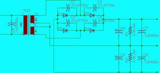
How did you arrive to the snubber caps value? I supose depends on which diode is used. I use soft recovery ultra fast types. Also the input 1uF cap, I see in some designs 100nF. I also see 1-2uF cap after the electrolytics in some schematics and sometimes a RC filter. Is there a way to arrive to the best values for this parts?
Thank you.
Unregulating the PSU
Hi guys,
I discovered my PSU was noisy that's why the jump for the regulated supply gave such good results. The highs became smoother and sweeter. This "noise" was perceived like an harsh metalic treble. I rebuilt the PSU according to drownranger and that metalic noise is now mostly gone. Being so, there's no need for a regulated supply with this amp. In fact, the amp has more bass with the unregulated supply.
I feel like I'm trying to find my way in the dark and you guys are the torches that light my path. That's why I make so many questions and sometimes do stupid naive mistakes. You have the experience and the knowledge that I don't have (yet) and I thank you for sharing it with me. 🙂
I'm now using the unregulated supply with 100nF MKP at the outputs and 100nF at each diode. I don't know if the noise is coming from the diodes, the transformer or the power company. But now it's better. Is there anything more I should do to improve further the PSU? Another question I'm wondering - why is that with the regulated supply the bass was not so strong and extended as with the unregulated one? 😕
Thank you for all your help. 🙂
Complementary PCBs
Hi all,
Kindly email me for consideration of complementary PCBs, they are about 10 of them or so. You will be required to pay for shipping. Hopefully thereafter PCBs will be available at the diyaudio shop at pocket friendly rates. The current time span is the next 5 weeks.
Yes its not too late to choose colors or make suggestions on mods. These suggestions should be in by the 17th.
kind regards,
Harrison.
Hi guys,
- why is that with the regulated supply the bass was not so strong and extended as with the unregulated one? 😕
Thank you for all your help. 🙂
it is strongly dependant on the power supply output impedance.
it is strongly dependant on the power supply output impedance.
I have tried LM338 besides LT1083 and I used the schematics from the datasheets. Same results, the bass is gone. So these regulators have an high impedance not good for audio use? I searched the forum and some people are using same regs and same schematics and nobody is complaining... only me. Only my bass notes are gone. 😕
Thank you, Nico.
Last edited:
Could it be the regs are too far away from the capacitor bank? I have about 30cm of wire between reservoir electrolytics and the regs.
Ok... it's saturday night and I'm here at home thinking about regs... something is not right🙄
Ok... it's saturday night and I'm here at home thinking about regs... something is not right🙄
Last edited:
Thanks, but is not a coupling cap issue. I use the same cap with regulated and unregulated supply. I decided not to use regulation because I don't feel the need for it anymore but I'd like to understand why with the regulator I have less bass.
Last edited:
PaulPT,
you must satisfy two criteria, the first is to have a low impedance regulator, and a fast regulator. One that can supply unrestricted the necessary peak current that your amp requires to drive the speakers. In fact the slew rate of the regulator should be at least as high as the amplifier itself.
One cannot split the power supply from the amplifier like in a simulation, it is an integral part. In fact you can say that the amplifier and the regulators are in series and each have to react equally instantaneously to a transient.
Designing a proper regulator is as difficult if not more so than designing an amplifier.
Why does capacitors seem to sound better, well simply put they can supply a lot of energy instantaneously. Problem is as they supply the energy the voltage drops and again sound is smeared since ripple will appear on the supply rail. A well designed regulator would sound even orders of magnitude better, remember you are not replacing the capacitors with a regulated power supply - you try to keep the rail voltage constant, therefore a regulated amplifier needs an even bigger and better power supply that an amp without.
Even a mediocre amplifier will perform miracles with a well designed power supply, something that few people here recognises, everyone is too concerned with how the amplifier simulates and whether there are five or six decimal places after the point in the harmonic artefacts.
Last edited:
- Home
- Amplifiers
- Solid State
- SYMEF amplifier