Jumper installed and voltages are up to 2.9V across the 100 ohm resistors.
😀
Now to try setting bias and test with a scope..
😀
Now to try setting bias and test with a scope..
Bias set. All is well. Here is a square 1 khz wave on board no 1.

Here is a triangular 1khz wave on board no 2:

Sorry if I have caused you to lose some time over this Al - I lost days!!
Now to put them in a nice case.
Here is a triangular 1khz wave on board no 2:
Sorry if I have caused you to lose some time over this Al - I lost days!!
Now to put them in a nice case.
Hi Aidan,
Don't worry about it. That pesky jumper. Boy did I ever try, while laying out the board, to avoid using it. Thanks for the waveforms, they look really nice. Should you need any further assistance, please don't hesitate to ask.
Best Regards,
Al
Don't worry about it. That pesky jumper. Boy did I ever try, while laying out the board, to avoid using it.
Thanks for the waveforms, they look really nice. Should you need any further assistance, please don't hesitate to ask.Best Regards,
Al
Last edited:
Hi Aidan,
Just wondering how your amps are coming along? Have you had a chance to listen to them?
Best Regards,
Al
Just wondering how your amps are coming along? Have you had a chance to listen to them?
Best Regards,
Al
Hi Al,
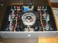
funny you should ask. I have just finished the casework.

Inside there's 4 amps - two Symasym 5.3 running off 30vac trafos, and two Symasym rev 1_3 running off 35vac trafos.
I have an active crossover and so the 1_3 boards drive the woofers and the 5.3 drive ribbon tweeters.
It's a great box in more ways than one. It won't fit in the cupboard. Some sorting is now necessary to house it.
The sound is off course superb 🙂
Many thanks for all your hard work AL. The next step is 4 way!
Aidan
funny you should ask. I have just finished the casework.
Inside there's 4 amps - two Symasym 5.3 running off 30vac trafos, and two Symasym rev 1_3 running off 35vac trafos.
I have an active crossover and so the 1_3 boards drive the woofers and the 5.3 drive ribbon tweeters.
It's a great box in more ways than one. It won't fit in the cupboard. Some sorting is now necessary to house it.
The sound is off course superb 🙂
Many thanks for all your hard work AL. The next step is 4 way!
Aidan
Hi Aidan,
Cool, we're both doing 4 ways. Nice enclosure.
I'll be going digital instead of active for the crossover using a 2 x In, 4 x Out MiniDsp, and my ES9018 DAC that I just got running. I'll stack two amplifier boards below the DAC to get four channels. I've attached a pic of my 4-channel SymAsym Rev_1.4 amplifier with an external PS, and the DAC playing music for the first time. The ES9018 is an amazing sounding DAC. I plan on making it available sometime next month if you're interested.
Good luck, keep me posted, I'll do the same.
Best Regards,
Al
Attachments

Last edited:
Hi Al,
There's noticeably more powerful easy bass from the rev 1_3 than the 5.3. I don't know how it compares at higher frequencies as I have only used it actively below 2.5khz.
I'm using vinyl so an analogue crossover is necessary. The amps are driven by a DCB1 which is also superb. Squeezebox into the DCB1 for digital.
For quite a while I thought about a digital crossover, so I'm very interested in how you are using the dac. Are you using the one dac chip to convert all 8 channels?
Current set-up is definitely the best I have had at home.
I have two more rev 1_3 boards which I'm planning to complete to drive a pair of 10 inch woofers.
regards
Aidan
Last edited:
How have you implemented the two different set ups?...........There's noticeably more powerful easy bass from the rev 1_3 than the 5.3............
What are the differences in component values?
Hi Aidan,
I'll configure the ES9018's 8 DACs to operate as four pairs to drive the four individual channels. Two I2S outputs from the MiniDsp will provide left and right channel low and high pass signal inputs into the ES9018.
Al
I'll configure the ES9018's 8 DACs to operate as four pairs to drive the four individual channels. Two I2S outputs from the MiniDsp will provide left and right channel low and high pass signal inputs into the ES9018.
Al
Last edited:
I got a pair board, planning to build a stereo set. What changes is needed to run the amp in 63vdc supply? This is the only supply i have. Tnx
Hi Josh,
Lateral mosfet as OT will work but you have to make sure you have the correct pinout, and somewhere between 220 and 470 ohms on the gate of each mosfet to prevent oscillation. I tried some BUZ lateral mosfets with 470 ohms on the gate and it worked great.
Best regards,
Al
Lateral mosfet as OT will work but you have to make sure you have the correct pinout, and somewhere between 220 and 470 ohms on the gate of each mosfet to prevent oscillation. I tried some BUZ lateral mosfets with 470 ohms on the gate and it worked great.
Best regards,
Al
Last edited:
Hi rapidvox,
63V rails is too high, it would require to many changes degrading the integrity of the design. The absolute max on the dual OT version would be 56V and that's pushing it.
Best regards,
Al
63V rails is too high, it would require to many changes degrading the integrity of the design. The absolute max on the dual OT version would be 56V and that's pushing it.
Best regards,
Al
Hi Al,
Thank you for the answer. I made symasym with good result, I like to make your AAK rev 1.4 with Mosfet output.
regards,
Josh
Thank you for the answer. I made symasym with good result, I like to make your AAK rev 1.4 with Mosfet output.
regards,
Josh
Hello all,
I've built up my 1.3 DTV boards but upon testing I smoked the 100 ohm test resistors on both channels. I checked and the bias pots were fully counter-clockwise. Rail voltage is around 37v, the power supply turns on fine (no fuses inserted on the board).
I never found a set of assembly instructions specifically for the 1.3 DTV so I looked at the squeal and 1.4 instructions. Were there any changes that had to be made to the PCB? It looks like the 1.4 boards had a few errors and I was wondering if something similar in rev. 1.3 could be causing the problem.
Thanks,
Nelson
After using my 4-channel AAK Symasym V1.4 happily for roughly 3 years now I'd like to do some changes to it:
1. I have some slight background noise on all the channels, it's running on 50V (35V secondaries) rails and biased at somethink like 50mV - so running pretty hot. Any advise is appreciated.
2. As I have changed the setup of my active system I'd need to reduce the gain on 2 of the 4 channels of 10 to 12dB, what resistors/values would need changing ?
I'll open it up after 3 years and give a quick check-over and would like to implement the changes to the gain and of course track down that slight noise issue.
Cheers,
Max
Last edited:
Hi Max,
Describe what you mean by slight background noise? Properly implemented Rev_1.4 should have an SNR of better than -100db with the inputs shorted. With your ears dug close to the woofer it should be dead quiet. The tweeter should have the slightest hiss with your ear right up to it. The hiss should be clean with no crackles or pops.
The bias at 40mv is too high, try 25mv.
Best regards,
Al
- Home
- Amplifiers
- Solid State
- SymAsym - "The Sequel", AAK's Rev_1.4 PCB Builders Thread