Hi Steve,
thanks a lot for confirming the non-issue of a shorted turn in this particular case.
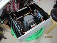
I added the second picture to make it clear, even if one can hardly see it, the bolt is NOT going throught both toroïds and NOT connecting bottom and top plate.
Thanks a lot to lgreen for the link and AndrewT for the technical background on shorted turns.
Cheers,
Max
thanks a lot for confirming the non-issue of a shorted turn in this particular case.
I added the second picture to make it clear, even if one can hardly see it, the bolt is NOT going throught both toroïds and NOT connecting bottom and top plate.
Thanks a lot to lgreen for the link and AndrewT for the technical background on shorted turns.
Cheers,
Max
Last edited:
Anyone having a mouser order pending and willing to forward 2 PS-caps to France?
Hi all,
actually my build in on hold as I am missing 2 of the UCC PS-caps.
I have absolutely nothing to order from mouser right now, and minimum postage to France is USD 20.
Is anyone willing to inclue 2 x the ref. EKMH630VNN472MQ50T in his order and forward them to me ?
I will gladly pay the components themselves, the postage/packing and any additional fees in advance if I can avoid paying USD 20 for 2 caps.
Cheers,
Max
Amp powered up..but having positive and negative DC offset
Hi everybody,
first of all I'd like to wish you all the best for the new year.
After completing the last PS-board (thanks Al for shipping the missing caps), we powered up the amps tonight and set the bias.
It takes quite a while for the the voltage to stablize and it drops about 5mV when the amp is warm.
We settled on 40mV on the warm amp and measured the DC-offset at the binding posts.
Two amps show a "positive" offset and the two other amps show a "negative" offset. Offset is between 5 and 10 mV for each amp and I was wondering if I should be worried about those different offsets ?
I didn't notice the pos. and neg. offset when testing the amp boards, but I was using a cheap DMM at that time.
Any hints ?
Cheers,
Max
Hi Max,
Happy New Year to you. Great to hear that you got the caps. Don't worry about the DC offsets being different. Your reading of 5 to 10mv for DC offset for each amp is very good. Good luck with the rest of your set up.
Best regards,
Al
Happy New Year to you. Great to hear that you got the caps. Don't worry about the DC offsets being different. Your reading of 5 to 10mv for DC offset for each amp is very good. Good luck with the rest of your set up.
Best regards,
Al
Amps running but "buzzing"
Hi,
well I just tested the amps and all 4 of them are running fine so far.
But I there are some issues:
First I have some hum from the speakers with RCA hooked-up and no signal.
Second, I have a buzzing sound from the speaker with no RCA hooked up.
And finally, when turning the amp off with the signal coming in, I get a bad crackling sound when the amp is fading while emptying the caps. No crackeling sound when the singnal is turned off.
Not sure if I have expressed myself, well.
Any help appreciated.
Cheers,
Max
Hi Max,
Try grounding the amplifier to the heatsink and see if that helps. You can use one of the two ground vias near C26 and C27, or one of the unused ground terminals T11-T13.
It's normal to hear a crackling sound as the caps discharge, especially if the audio input is playing at high levels. It's best to first turn off the music then power down.
Al
Hi FAA,
That's great to hear. Thanks for the pic, you did a really nice job.
I like the enclosure, where did you get it from?
Best regards,
Al
That's great to hear. Thanks for the pic, you did a really nice job.
I like the enclosure, where did you get it from?
Best regards,
Al
One channel gone bad...
Dear AL,
well, after hooking up the amp in the flat having proper earthing I don't get any hiss from the speakers, I must say they are round 91dB only.
Unfortunately one channel is not working properly, one fuse blew, and when replacing it the fuse of the other rail blews, and vice versa.
I disconnected the PS-board and it runs fine on it's own.
Any hints for troubleshooting are highly appreciated.
Cheers,
Max
Does anybody has and would like to sell me a couple sets (to complete two boards) of the required matched transistors? thanks
One amp board blowing fuses...
Hi Everybody,
after listening to the amp using 2 channels only I must say we ara very satisfied with the result.
We used to listen to the setup from my cousin Pierre (aka Waveflex) setup using 2 pairs of Rotel RMB-100 and we both agree that the Symasym is far more dynamic, say punchier.
Bass performance is outstanding!
On the other hand it's really straightforward, having far less coloration than the monoblocks.
Tonight I finally decided to take the amp on the bench to solve the problem we are encountering on one channel only.
The fuses on the PSU-board blow (one at the time only) and when replacing it the other one blows straight away.
I just interchanged the amp board and can definitely say it's the amp board messing around.
Anyone having a hint what the problem could be based on the symtoms described ?
Any hints for troubleshhoting it are highly apreciated!
Cheers,
Max
Last edited:
I was thinking about using a bunch of Sankens that I have on hand to replace the output/driver set in the Rev 1.4 board. The specs look fairly close on the surface to the Toshibas which are cheaper. The current versus Vce curves though look a bit different. For example, at 600ma and a Vce of .75V, the 2SC3264 is rated at 7.5A and the 2SA1943 pulls a little less than 6A. The transition frequency of the driver units is a little higher with the Toshiba but the Toshiba output units have a transition frequency nearly half that of the Sanken. Granted, these are only manufacturer specs and will certainly vary piece by piece but the numbers seem different enough to require some changes. Any thoughts?
http://www.sanken-ele.co.jp/en/prod/semicon/pdf/2sa1859ae.pdf
http://www.sanken-ele.co.jp/en/prod/semicon/pdf/2sc3264e.pdf
http://www.toshiba.com/taec/components2/Datasheet_Sync//66/7673.pdf
http://www.toshiba.com/taec/components2/Datasheet_Sync//66/7632.pdf
http://www.sanken-ele.co.jp/en/prod/semicon/pdf/2sa1859ae.pdf
http://www.sanken-ele.co.jp/en/prod/semicon/pdf/2sc3264e.pdf
http://www.toshiba.com/taec/components2/Datasheet_Sync//66/7673.pdf
http://www.toshiba.com/taec/components2/Datasheet_Sync//66/7632.pdf
how to order the kit and how much?
Hi AAK,
How can i order AAK 's Rev 1.4 PCB and how much..i'm in Philippines. Thank you in advance..
Boyet
Hi AAK,
How can i order AAK 's Rev 1.4 PCB and how much..i'm in Philippines. Thank you in advance..
Boyet
Can I test the BJT in circuit with my DMM diode tester ?
Hi everybody,
as mentionned one of my channels on the symasym stopped working, the symptoms are a blowing fuse. Once replaced the fuse of the other rail blows immediately.
My uneducated guess is a blown transistor.
Can I test the BJT in circuit with the diode function of my DMM ?
I gave it a try and get different readouts for the broken and the working channel.
Unfortunately none of the readouts fits the results I should get when using this tutorial:
Basic Testing of Semiconductor Devices
I guess this is due to testing in circuit ?
Someone please chime in as I would like to troubleshot the amp and am willing to learn.
Thanks in advance,
Max
P.S.: I could post the readout of my DMM here if they are worth considering.
Hi Max,
It sounds like the output transistors are blown. Set your DMM to continuity, and with the power off check each OT for shorts. Let me know what you find?
Best regards,
Al
It sounds like the output transistors are blown. Set your DMM to continuity, and with the power off check each OT for shorts. Let me know what you find?
Best regards,
Al
Last edited:
Hi AL,
thanks for your quick answer.
With my DMM set to continuity ("beep" mode) I can't find any shorted legs on the NPN and PNP, strangely for both the working channel and the broken one.
I am not sure this is the DMM setting you are referring to...the results does not seem to cope with my previous results using the "dioder tester" mode..
Should I post those results as well ?
Cheers,
Max
Hi Max,
The DMM is set correctly, when the probes are connected together it should beep. Did you check for shorts across each individual transistor pin? For example, place the red probe on the NPN transistors base, and the black probe on the emitter. If the there's a short the DMM will beep.
Al
The DMM is set correctly, when the probes are connected together it should beep. Did you check for shorts across each individual transistor pin? For example, place the red probe on the NPN transistors base, and the black probe on the emitter. If the there's a short the DMM will beep.
Al
Max, if you can't find any shorts on the OTs set your DMM to diode mode and connect the red probe to the base and the black probe to the emitter on each NPN OT. Do the same for the PNP OT but switch the probes so the black probe goes on the base and the red on the emitter. Let me know what you find? You should get a reading on your DMM somewhere between 0.4 and 0.5.
Al
Al
Hi AL,
actually I did all 6 possible combinations (not that it would matter in this DMM mode) using the 2 probes of my DMM on all the 3 pins of each device.
I once had a short beep.. for a fraction of a second but guess I was touching the probes... I could not repeat the phenomenon.
It's actually a DMM have a analog scale as well.. I'd say a combined one.
When probing B (red) -E (black) on the workig channel no reading at all, when testing the same on bad channel no digital reading but a faint swing and hold on the analog part.
Red is definitely the positive probe (I have tested a working diode).
Max
- Home
- Amplifiers
- Solid State
- SymAsym - "The Sequel", AAK's Rev_1.4 PCB Builders Thread