Transistors 2n5401 and 2n5551 that I have are chinese made "Jiangsu" anybody has experience with those? What do you think about using (2sc2240gr/2sa970gr). They have higher "hfe" than the originals.
I also have 2sc2705/2sa1145 with similar "hfe", but lower "Cob" and i don't know if that can be a problem.
Thanks
I also have 2sc2705/2sa1145 with similar "hfe", but lower "Cob" and i don't know if that can be a problem.
Thanks
Power rating emitter resistors
Hi
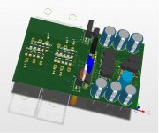
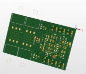
I´ve started an PCB design with mostly SMD parts. -> attachement
Could anybody advise which minimum power rating the output transistor emitter resistors must have?
I also want to use SMD parts for that.
Thanks in advance
Stefan
Hi
I´ve started an PCB design with mostly SMD parts. -> attachement
Could anybody advise which minimum power rating the output transistor emitter resistors must have?
I also want to use SMD parts for that.
Thanks in advance
Stefan
Attachments
I still have a few boards left for those interested.
Regards,
Al
Can I still order one pair for stereo amp?
Many thanks for the answer 🙂
I am inclined to the view that peak current survivability is more relevant to the emitter/source resistor.Could anybody advise which minimum power rating the output transistor emitter resistors must have?
If you are power testing the amplifier the resistor will have to pass a continuous half wave AC current. But that is an exceptional case that rarely if ever happens while reproducing music.
However, short term peak currents that are way in excess of the power testing current can pass through the emitter resistors.
Wirewound are very tolerant of this overload.
Metal and carbon film are not tolerant of this transient overload.
Many parallel connected smd resistors should have sufficient transient current capability. You either research previous works or do your own.
Hi Al(l),
slowly getting to the end of the build.
I would like to do the final testing this week-end and was wondering what the consensus is about the voltage on the emitters of Q22 & Q23 is.
35mV ? 50 mV ? higher ?
Anyone able to give me some insight on this issue ?
Thanks in advance,
Max
EDIT: Does the amp need to be under load, i.e. with a dummy load or speaker connected to set the voltage ?
Last edited:
Hi,
have you tested out the wiring previously?
Don't connect it direct to the mains.
Any error could destroy your amplifier at first power up.
Use a bulb tester for first power up.
Short the input RCA sockets. A dummy RCA plug with a direct wire link soldered from hot to shield tag does this.
Do not connect anything to the output not even a dummy resistive load.
Hi Andrew,
well I think we tested everything as per Al's procedere.
The PS is doing fine, putting out around +/- 52 volts without load and the amp section powered up fine showing only little DC offset.
So no bulb tester needed right now, but I will have to build one anyway for future projects.
What do you mean by "the wiring", the wiring from the board to input (RCA) and output sockets (binding posts) ?
Thanks for the hint of shorting the input, will do so.
Will post some pics of the baby shortly.
Cheers,
Max
any wiring, from the mains, or to the rectifier, or to the smoothing or to the amplifier, or to the soft start, or simply wiring the transformer primaries out of phase...............What do you mean by "the wiring", ?
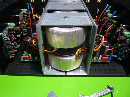
Good job coolnose. The only problem with your toroid mounting is that you appear to be enclosing the transformers in metal and fitting a metal screw through their centres. This amounts to a "shorted turn" electrically. Please do not power up if this is the situation.
Regards,
Steve
I think Currentflow's observation is correct.
Avoid the "Shorted Turn". It can burn out your transformer and will probably hum badly.
Avoid the "Shorted Turn". It can burn out your transformer and will probably hum badly.
Hi,
actually we used some stainless bolts for mounting the toroïds.
I supposed this would be enough to avoid shorted turns.
Furthermore this appears to be the "standard" mounting method provided by multiple suppliers, but without using stainless.
Could someone give me more insight on how the metal enclosure around the toroïs would cause a shorted turn ? Were are not talking hysterisis, are we ?
Thanks in advance,
Max
Hi Steve,
after your comments referring to "shorted turns" I read up some info I could find on DIYAUDIO and other supports.
If I understand it right I don't have a shorted turn in this case.
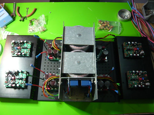
It's hard to see, but the lower toroïds are bolted to the ground plate, while the upper toroïds are suspended to the upper bracket, i.e. mounted upside down.
The toroïds on the same axis do not share the same bolt.
Looking forward to you comments.
Cheers,
Max
[url=http://www.flickr.com/photos/43699855@N03/5196050682/] [/URL]
after your comments referring to "shorted turns" I read up some info I could find on DIYAUDIO and other supports.
If I understand it right I don't have a shorted turn in this case.
It's hard to see, but the lower toroïds are bolted to the ground plate, while the upper toroïds are suspended to the upper bracket, i.e. mounted upside down.
The toroïds on the same axis do not share the same bolt.
Looking forward to you comments.
Cheers,
Max
[url=http://www.flickr.com/photos/43699855@N03/5196050682/]
 [/URL]
Last edited:
Hi,
actually we used some stainless bolts for mounting the toroïds.
I supposed this would be enough to avoid shorted turns.
Furthermore this appears to be the "standard" mounting method provided by multiple suppliers, but without using stainless.
Could someone give me more insight on how the metal enclosure around the toroïs would cause a shorted turn ? Were are not talking hysterisis, are we ?
Thanks in advance,
Max
This shorted turn thing comes up a LOT, here is a helpful article.
EE Times How to mount a Transformer
Imagine winding one turn of copper wire around the core of the toroid, i.e. down through the hole and up at the perimeter.
Connect a resistor between the two ends. Connect a voltmeter across that resistor.
Power on.
That one turn develops an EMF.
That EMF tries to drive current around the loop formed by the copper turn and the resistor.
The current that flows is determined by EMF of the loop (turn) divided by resistance of the loop.
Let's put in some numbers.
One Turn resistance ~2milliohm (0r002)
resistor 100r
one turn EMF ~500mVac
The voltmeter will read 500mV - 2milliohm*5mA = ~ 500mV
Current = 500mV / 100.002ohm ~ 5mAac.
Now omit the resistor by shorting together the two ends of the one turn.
Current is 500mV / 0.002ohms ~ 250Aac.
Now replace the copper wire turn with an 8mm diameter bolt and a big chunk of steel or iron chassis. Resistance of that could be 0.5 milliohm (0r0005).
Current through the bolt ~ 1kAac.
You must avoid the shorted turn.
Last edited:
This shorted turn thing comes up a LOT, here is a helpful article.
EE Times How to mount a Transformer
Hi lgreen,
thanks a lot for the link provided, interesting read ( not only I guess) for beginners.
I actually stumbled across one of your posts dated 2004 when checking for shorted turns.
Cheers,
Max
Imagine winding one turn of copper wire around the core of the toroid, i.e. down through the hole and up at the perimeter.
Connect a resistor between the two ends. Connect a voltmeter across that resistor.
Power on.
That one turn develops an EMF.
That EMF tries to drive current around the loop formed by the copper turn and the resistor.
The current that flows is determined by EMF of the loop (turn) divided by resistance of the loop.
Let's put in some numbers.
One Turn resistance ~2milliohm (0r002)
resistor 100r
one turn EMF ~500mVac
The voltmeter will read 500mV - 2milliohm*5mA = ~ 500mV
Current = 500mV / 100.002ohm ~ 5mAac.
Now omit the resistor by shorting together the two ends of the one turn.
Current is 500mV / 0.002ohms ~ 250Aac.
Now replace the copper wire turn with an 8mm diameter bolt and a big chunk of steel or iron chassis. Resistance of that could be 0.5 milliohm (0r0005).
Current through the bolt ~ 1kAac.
You must avoid the shorted turn.
Hi AndrewT,
thanks a lot for your calculations, I certainly understand the danger of a shorted turn under the circumstances described.
Thing is I don't think I do actually have a shorted turn...
Either it's too obvious for me to see or it's simply not there.
Considering the bolt of the superposed toroïds is not common to both of them I thought I'd have avoided it.
Could you confirm ?
Thanks,
Max
Hi coolnose,
I believe AndrewT has covered the theory behind the shorted turn very well. However, if the bolt stops between the transformers (i.e. it doesn't pass through two transformers in the same plane before touching the case floor) as you have indicated, then that is absolutely fine. There is no shorted turn in that case. Photos can be deceiving!
Regards,
Steve
- Home
- Amplifiers
- Solid State
- SymAsym - "The Sequel", AAK's Rev_1.4 PCB Builders Thread


