From the post above yours.😉I glued the matched pairs together using instant cyanoacrylic. Q1 to Q2, Q4 to Q12, Q3 to Q9.
Yes Ryssen Thanks, was reading the posts 2 ours..and it is just above!
I take some values for the 2n5551...with a digital multimetre.
hFe from 100 to 270..
are the higher values better ?
2X 270
1X 255
2X 246
4X 230
5X 100
6 between 110 and 150
From a stock of 20
For the 2 boards , what's the best configuration ?
JF
I take some values for the 2n5551...with a digital multimetre.
hFe from 100 to 270..
are the higher values better ?
2X 270
1X 255
2X 246
4X 230
5X 100
6 between 110 and 150
From a stock of 20
For the 2 boards , what's the best configuration ?
JF
Hi jef9200,
The higher gain is better, so the 270 pair and the 246 pair. You may find they are not as well matched as you think. There are other things you can do if you think there is a problem with the match on your pairs.
-Chris
The higher gain is better, so the 270 pair and the 246 pair. You may find they are not as well matched as you think. There are other things you can do if you think there is a problem with the match on your pairs.
-Chris
Hi,
Anatech and I seem to disagree on what parameter needs to be matched in a Long Tail Pair. This same argument also applies to the current mirror in the Symasym.
I contend that hFE matching using a DMM is worthless for this purpose.
Even hFE matching at the fixed quiescent operating current achieves poor LTP & Mirror matching.
Go match Vbe PRECISELY for a good matched pair.
I found that the mirror benefits from a slight Collector current mismatch of about 2% to 3% to make the LTP above it match in emitter currents. There is no emitter resistor available to check directly, so I can see only one method of approximating & it's done by adding and subtracting ALL the base currents that flow in and out of the two second stage LTP emitter load paths.
Hi Andrew,
Try this with the jig you made.
You will find that vBE are normally close. It is the hFE that is more important since this is your error corrector. A slight vBE mismatch is harmless and may cause a slight DC offset, but it will only be a couple mV (your vBE mismatch). The gain match is required for a diff pair (or LTP) to operate as designed.
Yes, we do disagree on this point.
-Chris
Try this with the jig you made.
You will find that vBE are normally close. It is the hFE that is more important since this is your error corrector. A slight vBE mismatch is harmless and may cause a slight DC offset, but it will only be a couple mV (your vBE mismatch). The gain match is required for a diff pair (or LTP) to operate as designed.
Yes, we do disagree on this point.
I agree with you if this is your final test. It is useful for pre matching previous to a better testing method.I contend that hFE matching using a DMM is worthless for this purpose.
I think that when you match hFE, you will see that vBE is close. I actually measure both base voltages in mV to determine if the hFEs are matched in a working circuit. If I find these voltages differ greatly, the hFEs will be out for sure.Go match Vbe PRECISELY for a good matched pair.
-Chris
Go match Vbe AND hfe PRECISELY.AndrewT said:
Go match Vbe PRECISELY for a good matched pair.
If you have BJTs from the same lot number Vbe has very little variation between transistors but Hfe is much widely distributed on a gauss (normal) curve.
Hi roender,
Yes, agree completely. I guess I have not been able to get my point across very well.
-Chris
Yes, agree completely. I guess I have not been able to get my point across very well.
-Chris
Final post (I hope).
I freed(sp?) up enough time to repair and update my monoblocs this weekend, and they are working so well I've been encouraged to enABLE my Fostex cones to see what the system is capable of.
Thanks, everyone for the help. With your assistance, I didn't make near as many mistakes as I would have on my own, and even came away from this project with a *slightly* better understanding of amp design and component function.
As a final gesture of appreciation, I'm listing below the changes I made to Al's BOM. I'm not sure how much difference the component substitutions make, but the end result is truly marvelous.
1) 5 watt Kiwame carbon film resistor at R4;
2) 5 watt Mills wirewound resistors at R27, R28, R37 and R38;
3) 0.5 watt Audio Note tantalum resistor at R13;
4) 0.5 watt Shinkoh tantalum resistors at R12, R14, R29 and R30;
5) 2 watt Kiwame resistors everywhere else they’d fit on the amp side of the board;
6) 500V Miconics silver mica caps, with a 5pF cap at C14;
7) V Cap OIMP cap at C1;
8) Rubycon ZL caps at C8 and C9;
9) Nichicon 35V KZ cap at C19;
10) Black Gate .47uF, 400V NX HiQ cap at C28; and
11) 10A, 300V CREE Schottky diodes at D1, D2, D3 and D4.
George
Quote :
I freed(sp?) up enough time to repair and update my monoblocs this weekend, and they are working so well I've been encouraged to enABLE my Fostex cones to see what the system is capable of.
And, finally, what was the cause of the failure ?
I freed(sp?) up enough time to repair and update my monoblocs this weekend, and they are working so well I've been encouraged to enABLE my Fostex cones to see what the system is capable of.
And, finally, what was the cause of the failure ?
The Rubycon ZL cap at C19 had failed.
Although I had denuded the cap and cut both leads short after installation, so I don't know if I had reversed its polar orientation or not.
hd38 said:Quote :
And, finally, what was the cause of the failure ?
Although I had denuded the cap and cut both leads short after installation, so I don't know if I had reversed its polar orientation or not.
Hi Colescuttle,
You weren't reading about tweaks were you?
-Chris
Why the devil would you do this???? I am completely at a loss here.Although I had denuded the cap and cut both leads short after installation
You weren't reading about tweaks were you?
-Chris
I was hoping to leave on a more positive note...
Ironic that I should be "outed" on the way out. Oh well.
I wasn't just posturing or being humorous about my "dummy" status, and, to tell you the truth, I think the mainstream audio freak is not much better informed. After all, it's audio dummies with too much expendable income who have made the purveyors of thousand-dollar-a-foot cable wealthy. Or worse, the hucksters who charge a hundred and fifty dollars for a three dollar rat shack digital clock THAT WAS CONFIRMED BY GOLDEN-EARED AUDIOPHILES IN OUR DOUBLE BLIND TESTS TO ALLOW A BOOMBOX TO ABSOLUTELY BLOW AWAY A $50K ALL TUBE VINYL SOURCE SYSTEM AND IT DOESN'T EVEN HAVE TO BE TURNED ON TO WORK ITS MAGIC ("magic" being the operative term). On the other hand, those of us dummies with too little expendable income turn inevitably to...tweaking.
Before discovering diy.audio, my knowledge of ee allowed me only to swap components, and, over many years I did find some "audiophile-approved" components (see former list) that sounded better than stock components. Then, on the chip amp forum, I was introduced to a whole new level of tweaking (probably because a chip provides the user with only a marginal opportunity to "tune" its sound). Wire type, gauge, brand and length; resistor type, size, brand and orientation (yes, I said orientation); capacitor type, brand, orientation (as regards non-polar caps), length of leads, and, yes, friends, "nudity," and other sundry, such as the tone imparted by the various metals used for heatsinking a chip.
Please don't ask me to catalogue the tweaks or their effects or why they're supposed to work, but some seem to make technical sense to an ee dummy, and, at worst, employing them is just a silly waste of time. At least until dummy installs a polarized cap backwards.
George
anatech said:Hi Colescuttle,
Why the devil would you do this???? I am completely at a loss here.
You weren't reading about tweaks were you?
-Chris
Ironic that I should be "outed" on the way out. Oh well.
I wasn't just posturing or being humorous about my "dummy" status, and, to tell you the truth, I think the mainstream audio freak is not much better informed. After all, it's audio dummies with too much expendable income who have made the purveyors of thousand-dollar-a-foot cable wealthy. Or worse, the hucksters who charge a hundred and fifty dollars for a three dollar rat shack digital clock THAT WAS CONFIRMED BY GOLDEN-EARED AUDIOPHILES IN OUR DOUBLE BLIND TESTS TO ALLOW A BOOMBOX TO ABSOLUTELY BLOW AWAY A $50K ALL TUBE VINYL SOURCE SYSTEM AND IT DOESN'T EVEN HAVE TO BE TURNED ON TO WORK ITS MAGIC ("magic" being the operative term). On the other hand, those of us dummies with too little expendable income turn inevitably to...tweaking.
Before discovering diy.audio, my knowledge of ee allowed me only to swap components, and, over many years I did find some "audiophile-approved" components (see former list) that sounded better than stock components. Then, on the chip amp forum, I was introduced to a whole new level of tweaking (probably because a chip provides the user with only a marginal opportunity to "tune" its sound). Wire type, gauge, brand and length; resistor type, size, brand and orientation (yes, I said orientation); capacitor type, brand, orientation (as regards non-polar caps), length of leads, and, yes, friends, "nudity," and other sundry, such as the tone imparted by the various metals used for heatsinking a chip.
Please don't ask me to catalogue the tweaks or their effects or why they're supposed to work, but some seem to make technical sense to an ee dummy, and, at worst, employing them is just a silly waste of time. At least until dummy installs a polarized cap backwards.
George
anatech said:I think that when you match hFE, you will see that vBE is close. I actually measure both base voltages in mV to determine if the hFEs are matched in a working circuit. If I find these voltages differ greatly, the hFEs will be out for sure.
-Chris
This is also my observation, at the beginning i also matched vbe and hfe, but at the end all my hfe-matches automatically had identical vbe's. (for non complementary matches)
Vbe matching for complementary devices was a pain in the a**, so i gave up on topologies needing complementary matches.
Mike
Hi George,
Well, you don't know unless you've tried it. Don't worry.
I really hope others do not remove the covering on these capacitors. In a few years you may need the information that was on these parts. You are intelligent enough to think about some of these claims before blind acceptance, so that's good.
The removal of the capacitor covering will not harm the cap unless, as you've pointed out, they are installed backwards. Make sure you keep all the documentation in a folder for future service.
-Chris
Well, you don't know unless you've tried it. Don't worry.
I really hope others do not remove the covering on these capacitors. In a few years you may need the information that was on these parts. You are intelligent enough to think about some of these claims before blind acceptance, so that's good.
The removal of the capacitor covering will not harm the cap unless, as you've pointed out, they are installed backwards. Make sure you keep all the documentation in a folder for future service.
You've summed it up well George. But remember, I have managed to install capacitors backwards with the markings left on! I wonder what that makes me?? 😉Please don't ask me to catalogue the tweaks or their effects or why they're supposed to work, but some seem to make technical sense to an ee dummy, and, at worst, employing them is just a silly waste of time. At least until dummy installs a polarized cap backwards.
-Chris
Re: The Rubycon ZL cap at C19 had failed.
Thanks for the info George and happy to know (as is your dog ?) it finally works fine ! I have followed many of your components choices.
Don't worry, even greatest men have had problems with Rubycon, Julius Caesar to name a few 😉
Andrew (from Scottish borders) is happier : Julius never went norther than Hadrian Wall 😀
Colescuttle said:
Although I had denuded the cap and cut both leads short after installation, so I don't know if I had reversed its polar orientation or not.
Thanks for the info George and happy to know (as is your dog ?) it finally works fine ! I have followed many of your components choices.
Don't worry, even greatest men have had problems with Rubycon, Julius Caesar to name a few 😉
Andrew (from Scottish borders) is happier : Julius never went norther than Hadrian Wall 😀
off topic again, sorry!
They did go farther North (the Antonine wall), but we frightened them off. Besides they probably considered it too cold to continue using their precious Togas.hd38 said:......... even greatest men have had problems with Rubycon, Julius Caesar to name a few 😉
Andrew (from Scottish borders) is happier : Julius never went norther than Hadrian Wall 😀
Aren't kilts even, ahem, airier than togas? 
Seriously George don't sweat it, I think you "graduated". I am sure many of us also went through that phase which is exactly as you describe: when you don't know enough to tweak things that matter (PCB layout, decoupling etc) you turn your energies to "doesn't hurt to try" tweaks, most of which matter zilch. I've been there too.
I don't know how y'all think about this but I am finding more and more that my own biggest last frontiers are, truly reliable quality solder joints, truly reliable quality connectors, truly smart grounding, and related circuit layout. I usually cobble it all together in a "proof of concept" way, and then once it works, I don't rebuild it properly - it just stays in the system until it (inevitably) something comes loose somewhere. Sigh.
Re: Re: The Rubycon ZL cap at C19 had failed.
Well, I can only hope that I won't meet my Nichicon any time soon.
hd38 said:
Don't worry, even greatest men have had problems with Rubycon, 😀
Well, I can only hope that I won't meet my Nichicon any time soon.
Re: Re: Re: The Rubycon ZL cap at C19 had failed.
Hmmm, I wont say the same if I met an Helena Seraphine ...
Ok, I stop to waste BW now 😉
Colescuttle said:
Well, I can only hope that I won't meet my Nichicon any time soon.
Hmmm, I wont say the same if I met an Helena Seraphine ...
Ok, I stop to waste BW now 😉
Hi all,
Fist board is playing !
45V/rails (2X 30V transfo 240V at home).
I used a little cd player with headphone output and it was a problem with trebble .. saturation ???
After i tried with a préamp and it was better but still a little saturation whith cds recorded at high level..
Now its running a few ours and its better...but...
I use a 10pf at C14, maybe the raison ?
There is some hum, too. javascript:smilie(' ')
')
My original symasym (first DIY project) was dead silent.
Bias: set at 25mv across r27 and r28. Is this correct ?
Newbie question: how can i mesure the Offset, i only have a DDM.
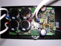
Here is a pic, maybe you can find a mistake ?
Thanks for this nice project ?
Perhaps i can build the second board with 5pf and compare ?
Fist board is playing !
45V/rails (2X 30V transfo 240V at home).
I used a little cd player with headphone output and it was a problem with trebble .. saturation ???
After i tried with a préamp and it was better but still a little saturation whith cds recorded at high level..
Now its running a few ours and its better...but...
I use a 10pf at C14, maybe the raison ?
There is some hum, too. javascript:smilie('
')My original symasym (first DIY project) was dead silent.
Bias: set at 25mv across r27 and r28. Is this correct ?
Newbie question: how can i mesure the Offset, i only have a DDM.
Here is a pic, maybe you can find a mistake ?
Thanks for this nice project ?
Perhaps i can build the second board with 5pf and compare ?
Attachments
- Home
- Amplifiers
- Solid State
- Symasym 5.3 "AAK model" builder's thread