I passed!
And moved up from "Dummy - Level 10" to "Dummy - Level 9."
Thanks, Mike. Since it's a b***h to pull the board off my heatsink-from-hell, I'll replace both at the same time, and since I was going to reflow the other board, I'll replace the ones on that board, too. That way, I can go ahead and match four 2N5551s and get these shipments off.
Time for a Guinness.
Hi George,
Somewhere around here is a small jig I made up for matching transistors. It can be built cheaply, but you will need a meter and a power supply or two. A couple 9V batteries might work as well.
-Chris
Somewhere around here is a small jig I made up for matching transistors. It can be built cheaply, but you will need a meter and a power supply or two. A couple 9V batteries might work as well.
-Chris
Thanks, Chris.
I still have the Duoyi matching meter, which works extremely well on a 6V supply if you can maintain a steady supply voltage (works best late at night).
I'm about to do my final match run and will ship the meter to Donovan tomorrow. Then I hope I resolve this c**p once and for all and start listening to music again.
George
anatech said:Hi George,
Somewhere around here is a small jig I made up for matching transistors. It can be built cheaply, but you will need a meter and a power supply or two. A couple 9V batteries might work as well.
-Chris
I still have the Duoyi matching meter, which works extremely well on a 6V supply if you can maintain a steady supply voltage (works best late at night).
I'm about to do my final match run and will ship the meter to Donovan tomorrow. Then I hope I resolve this c**p once and for all and start listening to music again.
George
Hi,
waiting for the postal strike to be over and get a pair of missing caps/4diodes for this first build.
But,
I have MJE15032/33 and MJE15034/5 for the drivers. I don't have MJE 15030/1.
Which of these have proved to be good alternatives?
or would a high gain 2sa649/c669 be an acceptable alternative?
waiting for the postal strike to be over and get a pair of missing caps/4diodes for this first build.
But,
I have MJE15032/33 and MJE15034/5 for the drivers. I don't have MJE 15030/1.
Which of these have proved to be good alternatives?
or would a high gain 2sa649/c669 be an acceptable alternative?
Sym-a-sym 101 (DUMMY alert)
Mike, Al, anyone...what is(are) the function(s) of the 220uF lytics at C8 and C9. Does their quality (impedance, etc.) have an effect on the way the amp sounds? I figure as long as I've got to pull the boards and replace parts a few additional ones wouldn't hurt, and I don't want to do this again (no more tweaking, no more tweaking...).
George
Hi Mike,
thanks for the prompt reply.
I'll go with the MJE 15034/5 for this first build.
Once I have it running successfully I can think about component value changes/alternatives for the subsequent builds.
Cole,
C8 & C9 are the voltage amp supply rail decoupling. They filter some of the modulation on the main supply rails. The bypasses (C10 & C11) are in parallel and film caps here pass most of the HF spikes to ground. The electrolytics pass the lower frequency modulations to ground. Low ESR would do. I suspect the film caps remove most of any audible differences. I'm using a parallel pair of 120uF, 50V, 105degC & unknown make on each rail.
Hi,
is there a schematic to go with AAK's PCB?
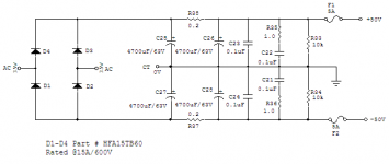
R33 through to R38 inclusive are all missing from the PDF I have to hand.
C27 & C28 are also omitted.
Why are R33 & R34 specified as 2W in the BOM? Even at +-40Vdc on the supplies they only dissipate 160mW.
Similarly, the snubbers R35 & R36 are 1W, why?
R10 =68r is passing about 5mA and dissipation is less than 2mW. Why the increase from 250mW to 500mW?
I have used 600mW metal film for all of these and the other 250mW resistors.
As far as I can see the only higher power resistors required are around the output, R27, 28, 4 & 7 should all be as specified.
I have used plastic mounted fuse holders. They foul the main smoothing cap locations. Can each of the fuse pads be moved outboard by about 0.5mm in the next group buy?
is there a schematic to go with AAK's PCB?
R33 through to R38 inclusive are all missing from the PDF I have to hand.
C27 & C28 are also omitted.
Why are R33 & R34 specified as 2W in the BOM? Even at +-40Vdc on the supplies they only dissipate 160mW.
Similarly, the snubbers R35 & R36 are 1W, why?
R10 =68r is passing about 5mA and dissipation is less than 2mW. Why the increase from 250mW to 500mW?
I have used 600mW metal film for all of these and the other 250mW resistors.
As far as I can see the only higher power resistors required are around the output, R27, 28, 4 & 7 should all be as specified.
I have used plastic mounted fuse holders. They foul the main smoothing cap locations. Can each of the fuse pads be moved outboard by about 0.5mm in the next group buy?
Hi,
I can't find here C1 in the same dimensions, so i'll solder a cap on the other side from the board .
I've seen here somebody using a big capacitor...what are the benefits of this big capacitor (v-cap ?)
Thanks.
JF.
I can't find here C1 in the same dimensions, so i'll solder a cap on the other side from the board .
I've seen here somebody using a big capacitor...what are the benefits of this big capacitor (v-cap ?)
Thanks.
JF.
Thanks, Andrew.
I'll leave them be, then.
George
AndrewT said:
C8 & C9 are the voltage amp supply rail decoupling. They filter some of the modulation on the main supply rails. The bypasses (C10 & C11) are in parallel and film caps here pass most of the HF spikes to ground. The electrolytics pass the lower frequency modulations to ground. Low ESR would do. I suspect the film caps remove most of any audible differences. I'm using a parallel pair of 120uF, 50V, 105degC & unknown make on each rail.
I'll leave them be, then.
George
Hi Andrew,
For R33 to R38 check the PS schematic below. Using lower power ratings for the resistor you mentioned are fine. At the time I used what I had available, I also use +/- 50V rails and wanted to keep R37 and R38 running cool.
Regards,
Al
For R33 to R38 check the PS schematic below. Using lower power ratings for the resistor you mentioned are fine. At the time I used what I had available, I also use +/- 50V rails and wanted to keep R37 and R38 running cool.
Regards,
Al
Jef, C1 and R13 are on the signal path when signal is at its lowest level.jef9200 said:Hi,
I can't find here C1 in the same dimensions, so i'll solder a cap on the other side from the board .
I've seen here somebody using a big capacitor...what are the benefits of this big capacitor (v-cap ?)
Thanks.
JF.
Hence, any distortion at this stage may have a big impact (as in the feedback loop where eg. C14 is also a critical component).
It could therefore be a good practice to populate C1 and R13 with the best available (audiophile ?) components.
Price is the limit, as is, IMHO, the fact that our poor ears are what they are and that our poor listening rooms acoustic is maybe a far more important space for improvement !
I will personally use Riken's as R13 and Wilmslow Super Sound caps as C1 (caps selected from french SCR brand capacitors) which seems to me providing a reasonable(affordable) quality/price ratio.
Hi Anatech,
following your advice to match hFE in the drivers, I have just measured and posted my results for 10 off each MJE15034/5.
http://www.diyaudio.com/forums/showthread.php?s=&threadid=109900
I have no hope of matching hFE.
Where now?
following your advice to match hFE in the drivers, I have just measured and posted my results for 10 off each MJE15034/5.
http://www.diyaudio.com/forums/showthread.php?s=&threadid=109900
I have no hope of matching hFE.
Where now?
Hi Andrew,
They are pretty tight within each number. Complimentary pairs are much worse, but closer than they used to be.
Don't you miss the 2SC2238A / 2SA968A days? I do.
If you take a ratio, they aren't great, but they are not as bad as others can be. 2:1 and worse used to be the norm. These are closer to 1:1.5.
-Chris
Hi, all
About heatsinks
If found 200X100X25 rth=0,9 (OK278/B/100) radiospare (10€)
or
200X100X40 rth= 0,6 (EM/B/100) radiospare (15€)
With 42V per rail, With one ?
What will be the power of the amp +- ?
About C1
May i use a Mundorf M-Cap for it ? (Mundorf MCap 400/250V, 3%) ? only 4€
Thanks.
JF
About heatsinks
If found 200X100X25 rth=0,9 (OK278/B/100) radiospare (10€)
or
200X100X40 rth= 0,6 (EM/B/100) radiospare (15€)
With 42V per rail, With one ?
What will be the power of the amp +- ?
About C1
May i use a Mundorf M-Cap for it ? (Mundorf MCap 400/250V, 3%) ? only 4€
Thanks.
JF
Hi,
C1 is part of the input filter. The value (not manufacturer) is important to passing/not passing the bass frequencies.
Either heatsink will do for cooling a monoblock. It will simply run at a different temperature.
The maximum power output will mostly depend on the transformer regulation. Expect between 60 and 70W into 8r0 for +-42Vdc @ quiescent current.
Hi,
the missing capacitors finally turned up.
Got the assembled PCB on test.
First power up using variac and light bulb and no fuses on the PCB.
all OK. +-39.8Vdc from 230:25+25Vac transformer
soldered 100r across each fuse location and powered up again.
with Vbe mutliplier off (max resistance) the Iq ~16mA (outputs off, drivers passing ~6mA).
Inserted F2A fuses. removed the light bulb and set supply to 240Vac. +-39.8Vdc. turned up the Vbe to get 25mV across the series pair of emitter resistors. +-38.7Vdc now with Iq set.
Output offset<0.9mVdc without any trimming (there is no adjustment on PCB).
Let it warm up, adjusted the bias back down from 28mV to 24mV. Rechecking Vac and Vdc at the output, 0 to 0.1mVac and 0.1 to 0.9mVdc, with input shorted.
With input open Vac jumps to 2 to 3mVac and stays below 0.9mVdc.
The output offset stability is impressive. From cold to warm with a variety of mains supply voltages it never strays outside the +0.1mVdc to +0.9mVdc. Not tried it hot yet.
I did cheat a little. I glued the matched pairs together using instant cyanoacrylic. Q1 to Q2, Q4 to Q12, Q3 to Q9.
Pity the PCB did not have these facing each other. It's so easy to layout for this convenience.
First impressions good.
Now to connect up dummy loads and oscilloscope.
- Home
- Amplifiers
- Solid State
- Symasym 5.3 "AAK model" builder's thread