Hi MBK,
Just some thoughts.
1. Disconnect the earth from power ground. Like MikeB said earth is evil and should be connected to the chassis only. From your THD plot it appears to me at 50Hz (AC main frequency) and harmonics there of that a ground loop is present.
2. With the amp input shorted, and unearthed. Do you hear any AC hum into a woofer, how about a tweater, do you hear a low level smooth sounding hiss, or a hiss mixed with some buzzing? It shoud be near dead silent if everything is working correctly.
3. If number 2 checks out, I'd play music and stay away from trying to measure THD using your lab top for the moment. Trust you ears to figure out if everything is working Ok.
With the problems you and Colescuttle and maybe others are experiencing, I'll try building one of my boards this week to make sure nothing funny is going on.
For reference, here's a THD plot of my prototype driving an 8ohm load at 60 watts at 1Khz.
Al
Attachments
After clarifying the bias adjustment method...
there's still no effect when I turn the trimpots. I suspect its down to the multiturn pots or the thermal trackers.
Either the BD139s are shot or I've fitted them the wrong way.
I'll be getting new ones and will reinstall them paying extra careful attention to orientation of the flying leads. I was counting on the 'e' marking on the board to mean 'emitter' of the BD139. I better reconcile the traces to the schematic to be sure.
Did you pay attention to the bd139 having "ECB" pinout? They have mirrored pinout compared to TO220/TO247 which have "BCE".
Mike
Mike
Thanks for the reply Mike.
I remember I was careful when I mounted it on the board the first time. It all went pear shaped when I had to remount them on the Sankens (pads got lifted upon removal). I soldered the BD139 leads to wires and they've been bundle shrouded in heatsink. Since the original pads have lifted they are soldered undeneath the pads of the following component up the chain. In all that confusion I must have forgotten whether theres 5 or 6 rounds in the chamber..
Anyway, I will have to redo them.
Hi cromodora,
Juse double checked, the "e" on the board is correct and marks where the emitter on a BD139 should go.
In post #155 it sounded as if could actually adjust the bias but with a limited range. Are the voltages across R27,R28 fixed at 15mv and 26mv, or does the bias change when adjusting R22?
Al
Juse double checked, the "e" on the board is correct and marks where the emitter on a BD139 should go.
In post #155 it sounded as if could actually adjust the bias but with a limited range. Are the voltages across R27,R28 fixed at 15mv and 26mv, or does the bias change when adjusting R22?
Al
Hi cromodora,
Never mind. I just read post #162. It can be a little confusing connecting the BD139 wires underneath the board. Hopefully that's all it is.
Al
Never mind. I just read post #162. It can be a little confusing connecting the BD139 wires underneath the board. Hopefully that's all it is.
Al
Hi Al,
ok, it's just that it leaves me no peace to not know what's going on! Anyway so i connected a 10" woofer and a tweeter. Still with earth connected, no laptop anywhere, inputs grounded, no hum, faint pink noise hiss audible at max. 1" off a 92dB/W tweeter. So far so good, this was the case even the first time I tried it, before I started measuring.
Now connecting a CDP (no computer, just a standalone Sony) via 20k pot: Some more hiss now, but likely cable pickup (I used an unshielded cable there), independent from volume. Test tones come across reasonably clear at up to 4 V rms, hard to turn it louder and hard to tell 0.2% distortion anyway by ear. So I could not resist... connected the USB soundcard just for measurement, still with the test CD from standalone CDP as a source. Unfortunately, same picture at 4V RMS, 0.15-0.2% THD, see below. This channel was the one retrofitted to Mike's BOM, which is identical to yours except for the lower base stoppers.
Attachments
Oh and with shorted inputs the woofer is completely inaudible.
Also, without any load but the voltage divider, my THD figures look pretty much like yours, in fact HD almost disappears in the soundcard's -90 dB or so noise floor and its own harmonics are about as high as the amp's. It's when there is >1V rms into 6 ohms that the trouble starts.
The plentiful PSU harmonics also only appear when there is a problem. See attached for no load of the very first measurement I made, earth, laptop and all, but no load.
Maybe the PSU is doing the oscillating. My PSU 0R2 RC resistor is also wirewound. An unlucky combo for an RLC circuit in a sensitive range?
Attachments
It's likely that you simply have a wiring problem, like too many grounds connected through everywhere.
Is the CDP earthed?
Do you have ability to loan a scope somewhere? That would really help to check if there are oscillations, and if, at which frequency they appear.
Is the battery powered laptop completely isolated from anything else, or does it have a connection somewhere else like printer, lan...
How does music sound? Lifeless/dull or dynamic/clear ?
Can you measure voltage across r8/9 and r26? (idle, no load)
What are your values for r4/c18?
Mike
For the measurements, the connection went like this:
Laptop: Battery, USB cable to external soundcard (M-Audio mobile pre), output with ground to amp, input from 6R load by taking signal from a 4700/120 R -32 dB voltage divider, no further connection to ground.
CDP: 2-prong plug, no earth, one channel output as the only signal wire going to it.
Amp: Signal from source via signal and ground wire to input. Output to speaker / load via larger gauge cable and output inductor. AAK's PCB has onboard caps, before them is 0R2 for filtering.
PSU: standard toroid 225 VA with 25 A bridge and suppressor caps to ground at the bridge. Earth connects at the junction of bridge and secondary center tap.
As far as I can tell there is only one ground path - earth is a dead end on the laptop side, and only one ground wire connects components at any time.
R4/C18 are your values, 4R7 metal oxide and 47n poly.
Scope: I wish... I'll ask around , maybe there is a chance.
Sound: I have a 3 way active system so I don't go very far with 1 channel; connecting the woofer only it sounded poweful but a bit too full; test tones had a slight distortion signature, actually consistent with 0.1 to 0.3% range I measured under load. That is, judging how these levels of distortion sound from the Sheffield test CD.
R8/9 and R26: I'll check tomorrow, it's 1 am here... I would just make a wrong move and fry something.
MBK,
You still need to disconnect earth ground from where it connects to your transformers secondary center tap. The amp including the PS has to be completely isolated from earth ground.
Al
You still need to disconnect earth ground from where it connects to your transformers secondary center tap. The amp including the PS has to be completely isolated from earth ground.
Al
Hi Al,
You can "relate' that connection to earth with a 100R resistor. There shouldn't be any current flowing in that loop for sure.
-Chris
You can "relate' that connection to earth with a 100R resistor. There shouldn't be any current flowing in that loop for sure.
-Chris
OK, so:
for bias ca. 75 mA, input shunted, no output load, not even cables:
on the channel with Mike's BOM (base stoppers: 22R and 1.2R, C14 10p, C3, 4=330p)
V R8 (22R)=1mV (0.045 mA)
V R26 (150R)=1.1V (7.33 mA)
on the channel with AAK's base stoppers: 100R and 10R, C3, 4=220p and C14=3.3p
V R8 (100R)=4mV (0.040 mA)
V R26 (150R)=1.16 V (7.73 mA).
This may all turn out a measurement issue... On some occasions plugging in the soundcard must have led to oscillations, by the sharply rising bias.
But I also found out, by testing a commercial Rotel amp (no earth) that I could reproduce the high HD picture with spray of high order harmonics on it. By using a differential probe on the soundcard and not connecting ground, this returned back to believable values, say HD at -75dB and only 2nd and 3rd harmonics. Not great but believable.
Now I re-tested the Symasym channels with the diff probe. Still HD at -60dB at 4V into load with spray of higher order harmonics, maybe 6 dB better with no load. This may well be an artefact. But it's still there when I use the CDP as a source, ground not connected to the soundcard (diff input only).
And finally I lifted Earth via the diode method. Only did listening tests so far with this config. Sounds pretty much the same to me, no audible noises on a woofer even with CDP on and plugged in on mute, and on a tweeter very low level noise. A previously present light buzz on the tweeter is gone now. Noise wise earth connection does not seem to make much of a difference. On test tones I still believe I can hear an added buzz, but that may well be the tweeter itself.
I must be living in a very electrically noisy environment because with laptop on batteries and nothing connected to soundcard but an open ended input cable I still get massive 50 Hz signal just by touching the leads of the input cable. No earth, no components connected, no amp, no CDP, just a lonely laptop and my fingers, and the potential between the floor I am standing on and the leads.
I guess I'll just finish my next 2 channels the way I first intended it, this gave me by far the best RTA picture into no load (see post #168), use them for the tweeters in my system, hope they won't melt anything, and leave the first two for experimentation for now.
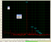
OK, just for the record. This is Mike's version except for R26 at 150 Ohms, 4Vrms into 6R
- amp psu: ground lift through antiparallel diodes, checked that not blown
- source: Sony CDP, no earth
- measurement: USB soundcard, laptop on batteries, probe is a balanced (differential) voltage divider -32 dB by 75 R / 3k with floating ground (NO ground between laptop and amp; measured at load resistor).
- Only one amp connected at a time of course and laptop wireless disabled.
AAK's is pretty much identical.
Note the huge 50 Hz peak. There ain't no ground, no line AC and no earth on the soundcard! (BTW I checked - turning fluorescent lamps in that room on or off, and fan on or off, doesn't change anything).
It's either the soundcard or something common to both. Or a transmitter. But I am in a windowless room in a concrete and steel house. And loopback measurements are pristine and amp harmonics are load dependent. What gives?
Attachments
Tried a few more random things:
- chenged transformer to an identical model
- shunted 0R2 series PSU resistor
- put transformer farther away from amps
none had an effect on HD spectrum or magnitude.
One thing had a significant effect: grounding the main heatsink. This gave a wildly fluctuating AC reading on the DMM across the load at 4V rms so I didn't even bother connecting the soundcard (signal source was the CDP). This was with the second transformer which was not yet converted to earth lift.
Hi MBK,
Grounding the heat sink is essential! Ground it to the common point in your power supply. Ungrounded heat sinks can cause oscillation in your output stage.
-Chris
Grounding the heat sink is essential! Ground it to the common point in your power supply. Ungrounded heat sinks can cause oscillation in your output stage.
-Chris
OK, here is something I did not know. They were meant to get grounded (actually earthed) in the final case but on the test bench they were not.
But: How come when I did it just now, out of sheer experimentation, I got just the opposite, instead of a steady 4V AC signal on the DMM (ungrounded) I got a fluctuating one (grounded)?
But: How come when I did it just now, out of sheer experimentation, I got just the opposite, instead of a steady 4V AC signal on the DMM (ungrounded) I got a fluctuating one (grounded)?
MBK said:... CDP as a source, ground not connected to the soundcard (diff input only).
Diff input does not work reliably that way (unless it uses a transformer), you still need a groundconnection to keep voltages in range.
BTW, are you using 2n5551 as inputdevices?
Mike
Yes I am a bit unhappy about the soundcard input. This outboard card has only balanced line in, and balanced / unbalanced mic in. The bal. mic in doesn't make sense (unnecessary gain and poor s/n ratio, and balanced). The unbalanced mic in gives awful harmonics even at lowest gain. And the balanced line needs severe workarounds.
When I use the soundcard as source there is a ground connection through the input ground, that's how I did most measurements: signal to one pin of the balanced in and ground from the soundcard output to amp connection. Attempts to ground the second balanced pin as it should be, failed: using a mono plug and grounding it at the amp end led to immediate immolation of the amp fuse. The mono plug should ground the second pin at the soundcard end but it does not do so: the sleeve is floating!
Anyway usually I use the balanced in in single ended mode as above, with unbalanced out ground as ground and this usually gives me OK readings. I only tried the balanced mode here out of desperation.
And yes, I use 2N5551 as inputs as well. Rails are 37.8V with near 10,000 uF caps.
I'll have to give the grounded heatsinks a better try with a solid connection to see what that achieves...
Ground yer heatsinks
Hi Chris,
you're the man. Can I buy you a beer or something? Anytime you're in Singapore? Maybe two? I grounded the heatsinks properly this time, with a commercially crimped earth lead to mounting bolt at the heatsink, and soldered to the point of entry of PSU ground to the PCB. At last I get a decent RTA under power and with very low noise as well. Seems my measurement setup is not completely out of whack after all.
Tested the board with Mike's BOM only so far, will revert changes to my initial build first and check again because C14 "should" be better at 3.3p (haha). HD is not quite as low as AAK's reference but I can put this down to remaining soundcard connection issues and the residual distortion of the not quite state of the art soundcard (it is darn robust though in taking abuse). No high order HD.
It is still twitchy though: I had to use the differential probe again because returning probe ground via soundcard output to the board input (where the feedback ground connects), again gave me a jump in bias current. Fine with the balanced probe though. I used the worst case setup, soundcard as source and earthed PSU.
Of course sans scope I can't verify residual small scale oscillations but at least now I can start listening.
I tested 4, 8, and 16V into 6R. Attached is 8V (10W). There is a 3 dB rise in 3rd at 40 W (16v).
Bias takes a long time to recover after roasting the heatsinks at 40W output for 10 minutes, they must get up to 60-70 degrees C. Bias collapses to a 3rd of the set value when turning signal off after that, because the drivers have their own heatsinks I presume, and don't track the output heatsink.
Thanks again for the tip, hope this really turns out to be the fix.
Attachments
- Home
- Amplifiers
- Solid State
- Symasym 5.3 "AAK model" builder's thread