Not only I have lost that very small diode, but also I'm unable to find that BZX585-B4V7,115.
Please help! Can a BZX384-C4V7.115 NEXPERIA (https://www.tme.eu/it/details/bzx384-c4v7.115/diodi-zener-smd/nexperia/) be a valid substitute?
Only a dozen of components (I've forgot, I have ordered of the wrong size, I have lost) is missing to complete the project and I'm trying to minimise the shipping expenses (impossible if I order something on Mouser, something on DigiKey, something on TME).
Last edited:
The BZX585 and BZX384 are electrically equivalent. The BZX384 is in a SOD323 package, larger than the SOD523 package of the BZX585 series. If you can get the SOD323 to fit the board then the BZX384 is a good substitute.
I have completely updated and re-issued the nx-Amp BOM to reflect currently available parts. A zip file has been added to the first post in this thread, and the nx-Amplifier page on my website has also been updated to reflect this and the file is below for your convenience.
This should breath new life into the nx-Amp of which about 250 have been built in its V1 and V2 guises (V2 is about 130 ). High quality PCB sets are still available from Jim's audio here nx-Amplifier PCB Set
Any questions or assistance needed, just shout.
🙂
This should breath new life into the nx-Amp of which about 250 have been built in its V1 and V2 guises (V2 is about 130 ). High quality PCB sets are still available from Jim's audio here nx-Amplifier PCB Set
Any questions or assistance needed, just shout.
🙂
Attachments
Wonderful! Thank you!I have completely updated and re-issued the nx-Amp BOM to reflect currently available parts. A zip file has been added to the first post in this thread, and the nx-Amplifier page on my website has also been updated to reflect this and the file is below for your convenience.
This should breath new life into the nx-Amp of which about 250 have been built in its V1 and V2 guises (V2 is about 130 ). High quality PCB sets are still available from Jim's audio here nx-Amplifier PCB Set
Any questions or assistance needed, just shout.
🙂
I'm cheching the PSU BOM.Wonderful! Thank you!
You suggest the 512-BC546BTA, that is not available on Mouser. The 512-BC546BTF seems a good substitute.
You suggest the 277-1263-ND from DigiKey, but, always in the spirit of minimising the shipping expenses, I see that on Mouser the 651-1868733 looks equivalent. 54 available. Me, I have used 651-1872392 on my PCB and they fit well. 50 available on 31/01/2022.
Hope it helps.
Thanks for your input. I will take a look in the morning and update or add this info.I'm cheching the PSU BOM.
You suggest the 512-BC546BTA, that is not available on Mouser. The 512-BC546BTF seems a good substitute.
You suggest the 277-1263-ND from DigiKey, but, always in the spirit of minimising the shipping expenses, I see that on Mouser the 651-1868733 looks equivalent. 54 available. Me, I have used 651-1872392 on my PCB and they fit well. 50 available on 31/01/2022.
Hope it helps.
Two comments:
R17, R18, R19, R20, R23, R23 are in the Zobel network and they are 2W resistors, while in the notes you write "0.5 to 0.6W 10mm lenght"
R25 : now you write "DO NOT INSTALL", I have already soldered it, what I should do?
Thanks
R17, R18, R19, R20, R23, R23 are in the Zobel network and they are 2W resistors, while in the notes you write "0.5 to 0.6W 10mm lenght"
R25 : now you write "DO NOT INSTALL", I have already soldered it, what I should do?
Thanks
The 33 Ohm resistors I specified are rated at 1W but are 10mm long - so the old style 0.5W/0.6W MF size.
1W 33 Ohm Reasistor
R25 is a 22 Ohm resistor across the ground lifter. No need to install it. If you have installed it, just leave it there.
🙂
1W 33 Ohm Reasistor
R25 is a 22 Ohm resistor across the ground lifter. No need to install it. If you have installed it, just leave it there.
🙂
So I just completed building the amp, with boards purchased in 2014 lol. Yes its been a long time. They are Jim's boards Rev 1.0. Biased fantastic and DC offset great, no issue until I tried measuring maximum power into my load bank. Both channels are clipping around 40 watts, I have double checked all my calculations and connections and everything seems good. Low power distortion is spot on. I am using a 800va Transformer and the Rails are +-46.2 vdc at the amp when its clipping, so voltage seems good. I'm kind of at a loss on where to check now?
Thanks!


Thanks!
Can you post up your calculation?
to check your working
(((Vpeak * 0.707)/Rload)^2)* Rload
40 V peak (=80V pk-pk) into 8 Ohms is about 100 W RMS
to check your working
(((Vpeak * 0.707)/Rload)^2)* Rload
40 V peak (=80V pk-pk) into 8 Ohms is about 100 W RMS
I'm using REW for the calculation to watts. But it's clipping just before 19 vrms output into 8 ohm load. Which is 45 ish watts. Also on the scope it's the top of the waveform that goes crazy. Both channels are the same and if I switch to 4 ohm load I'm clipping at the same Voltage but around 90 watts RMS. So basically half the wattage I should be getting.Can you post up your calculation?
to check your working
(((Vpeak * 0.707)/Rload)^2)* Rload
40 V peak (=80V pk-pk) into 8 Ohms is about 100 W RMS
Here is a couple more screen shots of the scope and FFT before and after clipping, 543mV and 581mV input voltage. This is into 8 ohm load. Thanks for the help.


I’ll have to look in more detail tomorrow (got grandson and family here now 😊) but you have something serious there. Are you sure the 15 Ohm resistors in the supply rails are 15 ohms?
I can confirm that R22 R23 R30 R31 are 15 ohm, and measure the same. I just pulled all transistors to double check and they are all good. I used the updated 120 ohm and 150 ohm resistors, hopefully that is not an issue since this is a REV 1.0 board. I also replaced the 547C and 557C transistors with 546B and 556B except Q20 which is 557C. Also here are some pics of 1 board.
Attachments
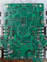
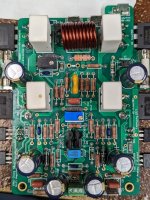
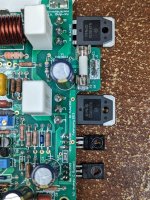
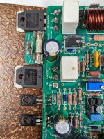
Ok. Tomorrow we can do some voltage measurements to check what’s going on.I can confirm that R22 R23 R30 R31 are 15 ohm, and measure the same. I just pulled all transistors to double check and they are all good. I used the updated 120 ohm and 150 ohm resistors, hopefully that is not an issue since this is a REV 1.0 board. I also replaced the 547C and 557C transistors with 546B and 556B except Q20 which is 557C. Also here are some pics of 1 board.
Merry Christmas I know it's a busy day and time of the year but if you get a free moment to guide me on some test points so i can get some data and see what's happening with the amp boards. Thanks againOk. Tomorrow we can do some voltage measurements to check what’s going on.
Just a suggestion: If you haven't already done so, then re-check all resistors and diodes - especially on the "upper half" of the board.
Is there a possibility if the 2SC3503E transistor is possibly counterfeit it could cause this issue? Reason being is I looked back through my records, and this is the only component I purchased from ebay. I'm not sure how to tell if they are, but here is a picture, and some data from my Peak Atlas DCA75 Pro
Attachments
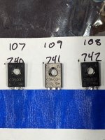
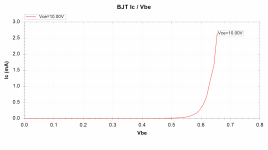
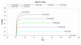
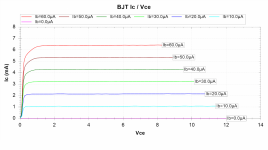
The gain on that looks a bit low (I get ~108). But, you also don't know how the device is behaving as the Vce increases as ther amp output swings between the two rails. The +ve side spike almost loops like the device is 'snapping' to some kind of short circuit mode.
I earnestly recommend that you never ever buy parts off eBay - always stick to mainstream disti's like Mouser, Digikey, RS etc. You do pay more, but you know what you are getting.
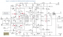
Below is a circuit diagram - you should check all your quiescent DC voltage against this with no input signal.
If the voltages are all ok, try please try this:
1. Connect the PSU to the amp (especially the Zobel connections - do not leave these off. Make sure the wires to and from the amp module are tightly bundled together
2. Run the amp with no load and a 1kHz input signal and see if it swings up to the rails - if it does, I would suspect the driver gains are dropping off at higher currents load currents. Check the 0 Ohm jumpers - make sure they are 0 Ohms and have not been damaged and gone high R during assembly.
Come back and let us know what you have found (are both channels behaving like this?)
I earnestly recommend that you never ever buy parts off eBay - always stick to mainstream disti's like Mouser, Digikey, RS etc. You do pay more, but you know what you are getting.
Below is a circuit diagram - you should check all your quiescent DC voltage against this with no input signal.
If the voltages are all ok, try please try this:
1. Connect the PSU to the amp (especially the Zobel connections - do not leave these off. Make sure the wires to and from the amp module are tightly bundled together
2. Run the amp with no load and a 1kHz input signal and see if it swings up to the rails - if it does, I would suspect the driver gains are dropping off at higher currents load currents. Check the 0 Ohm jumpers - make sure they are 0 Ohms and have not been damaged and gone high R during assembly.
Come back and let us know what you have found (are both channels behaving like this?)
Attachments
- Home
- Amplifiers
- Solid State
- SX-Amp and NX-Amp