Hi Jason,
Thanks for the help. Now on to the other board. I hurt it last week with a slipped test lead so I will probably be exchanging a few parts but shouldn't be too bad now that I have this one to compare to. Looking forward to getting both sides up and running so I can listen to some proper music through it. I also want to see how much heat sink it requires. I'd like to install it on some smaller ones if I can. Tired of building such tall amps.
Blessings, Terry
Good news. I sent my spice file to a friend and he said to try piggy-backing a 1k resistor on R1. Worked perfectly. Now I can adjust the offset to 0.0 and all the voltages look symmetrical. Playing music on one of the boards right now. I guess I probably need to cut the jumper on the input and will still need to get the speaker protect part of the PSU board working but at least I have figured out the offset issue.
Thanks for all the help.
Blessings, Terry
😎

Glad you got it to null Terry. I am concerned though that you had to reduce R1 to 1k.
But, let's get your amps up and running, I'll build a set of Stanton's boards over here and hopefully we can compare notes.
NB don't skimp on the heatsink.
But, let's get your amps up and running, I'll build a set of Stanton's boards over here and hopefully we can compare notes.
NB don't skimp on the heatsink.
Hi Andrew,
It probably didn't need to go all the way to 1K I had to adjust the trimmer quite a way to get to it to settle at 0.0 . It is not real steady there though. It varies with temperature and is still very sensitive to DC on the input. Works fine with a CD player on it however.
We'll see how the other board reacts once I get it fixed.
Thanks, Terry
It should be VERY VERY stable. I hope there is not a problem with the PCB's - e.g. a hairline crack or a barrel missing or something. My boards have not arrived yet - as soon as they do I'll take a careful look before assembling.
With 1k for R1, it means you can pump up to +- 10mA into the summing junction at the extremes - but the diamond buffer is only running at 1mA. You should only need a few 10's or at most 100uA or so trim the OP to zero.
With 1k for R1, it means you can pump up to +- 10mA into the summing junction at the extremes - but the diamond buffer is only running at 1mA. You should only need a few 10's or at most 100uA or so trim the OP to zero.
Bonsai,
I was forwarded an .asc file that exhibited the offset that Terry was experiencing and went about looking for a fault / cause for the issue. The simplest 'solution' was to allow the injection of more current from the offset adjustment network.
The circuit seems very sensitive to matching in the front end, particularly Q9 and Q11, and the overall gain of these devices also appears important. I was able to get acceptable offset by making copies of the spice models and altering the BF parameter, the higher and more equal the better. Could it be that Terry has devices that are on the lowish end of the gain spectrum and just poorly matched?
I haven't been following along; I'm jumping I'm very late here, so please forgive me for that.
Jason, could be- but the issues Terry sees seem far too fundamental in my view. He's matched the front end devices, but needs to inject huge offset currents to get the amp to balance which I find troubling.
Let me build a set of boards and then I'll be able to comment more fully.
Interesting problem!
Let me build a set of boards and then I'll be able to comment more fully.
Interesting problem!
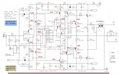
Yes I did match the transistors at least hFE. I don't think I quite needed 1k for R1. 5k may have done it. I just know I was at the end of the adjustment and I still had -340mv offset. I actually piggy-backed a 1k3 resistor onto the 10K because that is what I had on hand. I may try using a 5K in there instead and see if I can zero the offset while having the adjustment a little less touchy. I'm going to sit down this morning and mark up a schematic with some readings so I can get the second board worked out. I'll post what I have so you can look it over and make sure I don't have the bias too high on the VAS or front end.
Blessings, Terry
Blessings, Terry
OK I found the issue with the second channel. Q20 & Q3 were blown. Both channels are playing nice now. It sounds pretty good. I'm going to let it play for a few hours. Looks like the heatsinks I have it mounted to are about right. I'll just stick with them.
It will be interesting to see if your Stanton boards will work with the 10k in R1. I'll be watching.
Blessings
Blessings
Q6 Vbe is far too high.
Q7 Vbe is not stated.
0.4Vr30 indicates ~27mA. That gives ~1.2W in the transistors. Not excessive.
What accident blew the Vbe multiplier?
Q7 Vbe is not stated.
0.4Vr30 indicates ~27mA. That gives ~1.2W in the transistors. Not excessive.
What accident blew the Vbe multiplier?
Hi Andrew,
Thanks for looking things over. I should probably do a schematic with vbe readings. I have found that sometimes the voltage readings don't give a good indication of that because the probe will cause a jump in voltage.
The VBE multiplier got damaged because my probe tip slipped and shorted two resistor leads together. that was a few days ago.I had noted it in a post when it happened. It took out some front end transistors too. I replaced those right after it happened but when that didn't fix it, I set it aside and concentrated own the other board so I could find an answer to the offset issue I was having. Once I found the cause of that then I was able to return to the damaged board and look for the problem. Both boards are playing nice now. The sine waves look good on my scope. First listening impressions are that the upper mids are a little peaky. I'm hoping that will smooth out as it burns in a little more.
Blessings, Terry
Good week for me this one
Lost my iPhone in the taxi
Ordered nx-Amp PCB's a few weeks ago . . . . and I did not see that the default ship to address was to where I lived 7 years ago. I wont be seeing those for sure.
I've re-ordered today, so I am not going to be able to build my second nx-Amp for at least another 10-14 days.
My opinion on Jim's audio PCB's so far. Finally assembled all the boards. The amp boards are working but I must say are extremely time consuming to adjust properly. The Iq and DC offset's are very temperature dependent and so heat sinking plays a major role. Takes 30-45 min to stabilize even with big heat sinks. Too much hassle I think for an AB amp! Both amp boards behave similarly. Too "sensitive" for my tastes. The PSU works okay but the speaker protect still giving problems. (See earlier posts). Even after the delay engages (D15 on), the SSR does not appear to trigger on (20KOhms across in/out), played with rails from 40 to 50V. Don't know why yet.
It will be interesting to see how you make out with Jim's boards if ever you get them, Bonsai!
Cheers.
It will be interesting to see how you make out with Jim's boards if ever you get them, Bonsai!
Cheers.
The second set has been ordered and will be here by the week end. I am really surprised at these issues. I've built 5 boards and they all worked superbly - non of the issues you mention. But, let be assemble a set and see what gives. His boards were built with exactly the same Gerbers that I used.
You have to let the heatsink temp settle to something close to its final operating temp. If you go adjusting the Iq every minute or so, it will take time. Just drive the amp, get the sinks hot, then adjust the Iq and offset. All you need to watch for during this is that the Iq does not go too high.
The amp WILL have a DC offset when you turn it on of 20 to 50 mV. But after a few minutes, quickly settles to 1-2 mV. Ditto the Iq.
Have you got a pic of your heatsinks?
Last edited:
I haven't used any of the "additional" features of the PSU. So far I have only used the V+, V- and ground. I did notice that the LED is instant on, no delay. I will have to order some 3.3uf caps an try that. I'm not really sure if I care about a delayed on for the speakers but I do like the DC and short circuit protection. I'm surprised jprco's boards worked with the 10k in R1. I tried everything I could think of including replacing all of the transistor twice it wasn't until I lowered R1 was I able to get the dc offset under control. I wondered about the thermal wander. All of my devices came from either Mouser or direct from ON semi. I did use MJL's for the outputs rather than NJW's. Not sure if that could be a factor.
Let me build another set Terry with Stanton's boards. Cleary there's something going on here and I need to get to the bottom of it.
Just a note on the side. I have had problems with some boards from Jim's Audio and have emailed him in the past to correct them but I still see same errors on boards. One was the dual voltage PSU and speaker protect PCB. The screen showed a diode in the Spkr Protect oriented the wrong way. On a different Amp board, some copper traces were actually overlapped/ touching!
The Ovation boards looked fine to me the only thing that I could say was some of the "through holes"/barrels were really really small. Anxious to hear back from Bonsai.
Terry, I had no DC offset problems with either boards only the temperature drift and as Bonsai said, it just takes time to reach stable temperature.
The heatsinks are custom built and consist of 2 sinks (80Wx240Lx22H mm) attached to an aluminum plate (160x240x5mm) one per amp board. I've used similar (longer) ones for FC-100 amp which really heats up!
- Home
- Amplifiers
- Solid State
- SX-Amp and NX-Amp