Ivan,
Yes I will add that - thanks for pointing it out.
(Moderator, can you merge those threads into this one or redirect posts over there to this one? Thanks)
Yes I will add that - thanks for pointing it out.
(Moderator, can you merge those threads into this one or redirect posts over there to this one? Thanks)

Updated list:
PMI (2 nx-Amp + 1 nx-PSU)
ivanlukic (2 nx-Amp + 1 nx-PSU)
pinnocchio (2nx-Amp + 1 nx-PSU)
fab (2 nx-Amp + 2 PSU)
evette (2)
potepuh (2)
JethroTull (2nx-Amp + 2nx-PSU)

The first circuit boards for nx-Amp are expected in my hands on Monday or Tuesday, and I will post pics here when I have them.
The power supply board will take a few days longer, b/c I did not have time to review and order both simultaneously.
Also:
If anyone has comments about the parts list for either board, please post them here, especially if you think you may not be able to get a component in your country of residence, or for a reasonable price, or shipping cost. I am generally willing to ship a few parts along with the boards, but shipping/mailing costs make it very difficult to do it separately.
PMI (2 nx-Amp + 1 nx-PSU)
ivanlukic (2 nx-Amp + 1 nx-PSU)
pinnocchio (2nx-Amp + 1 nx-PSU)
fab (2 nx-Amp + 2 PSU)
evette (2)
potepuh (2)
JethroTull (2nx-Amp + 2nx-PSU)
The first circuit boards for nx-Amp are expected in my hands on Monday or Tuesday, and I will post pics here when I have them.
The power supply board will take a few days longer, b/c I did not have time to review and order both simultaneously.
Also:
If anyone has comments about the parts list for either board, please post them here, especially if you think you may not be able to get a component in your country of residence, or for a reasonable price, or shipping cost. I am generally willing to ship a few parts along with the boards, but shipping/mailing costs make it very difficult to do it separately.
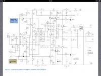
DIY-ers here did sim for nx. They are getting 68mA through VAS transistors and gain 18x. What could be wrong?
Screen shot is attached for the circuit they simed.
I can only check when I get back from my travels late tonight, or tomorrow
Thanks
R13 is the low noise ground isolation resistor. For the sim, you should short it out. These your gain will be 1+ 540/15.
The TIS/VAS current is set HIGH in this design so that the loading of the output stage forms only a small part of the TIS/VAS current.
The TIS/VAS current is set HIGH in this design so that the loading of the output stage forms only a small part of the TIS/VAS current.
Hi Bonsai,
in the NX manual you mentioned 25 mA through VAS: Q3 acts as the shunt pass transistor, conducting most of the TIS standing current which is about 25 mA in this design.
in the NX manual you mentioned 25 mA through VAS: Q3 acts as the shunt pass transistor, conducting most of the TIS standing current which is about 25 mA in this design.
Jorgo,
I can only look into the problem when I get back from my travels. Please wait until I can check and come back. The current does seem higher than I recall and I would have put the correct vs
Ue in the document. The sx- Amp TIS current runs higher.
I can only look into the problem when I get back from my travels. Please wait until I can check and come back. The current does seem higher than I recall and I would have put the correct vs
Ue in the document. The sx- Amp TIS current runs higher.
Last edited:
Ivanlukic just pointed out the rails on the schema are shown as 20V. Should be 50V max. On my version they are 48V ( measured).
Sim are made with 45V rails.
What I found that gain and current trough VAS in this amplifier largely dependent on the used transistors (their hFe) on positions Q9 and Q11 (looking Bonsai circ). With BC550C/560C gain is 18x, current through VAS is 68mA. With 2N5401/2N5551 gain is 36x, Ivas = 3.8mA.
If BC5xxC is used, than must change R30 and R31 from 15R to 100R to get Ivas = 14mA and gain 36x.
Last edited:
Sim are made with 45V rails.
What I found that gain and current trough VAS in this amplifier largely dependent on the used transistors (their hFe) on positions Q9 and Q11 (looking Bonsai circ). With BC550C/560C gain is 18x, current through VAS is 68mA. With 2N5401/2N5551 gain is 36x, Ivas = 3.8mA.
If BC5xxC is used, than must change R30 and R31 from 15R to 100R to get Ivas = 14mA and gain 36x.
No, that is not correct Jorgovanko.
The gain is set by R11 and the 540 Ohm feedback resistor - in the sim you have added R43 which is the front end ground isolation resistor. If you short out R43 as you should do in your sim the gain is 37x or 32 dB which is correct. The amplifier gain is not determined by the transistors used, but by the feedback resistor ratios.
You are right about gain (I did not connect the signal generator to the SGND, but to PGND), but current trough VAS is too much dependent of used transistor Q9 and Q11 (their hFe). Offset also. Why is this so?
Last edited:
I will check it later -you will see shifts, but should not be as big as you note. Your models need to be fairly accurate for this kind of analysis.
Can your sim show the effect of having different hfe in the two complementary driver transistors?...current trough VAS is too much dependent of used transistor Q9 and Q11 (their hFe)....?
I understand the mechanism at work here, but I have no numeric results for how much difference this will make when taken together with the whole circuit.
I ask because I can get some KSC3503E transistors for complementary pairs, but with some extra cost (shipping the parts twice, some paperwork, etc)... Don't really want to do it for no good reason, and I do not know how others building this amp feel about that... no point in testing with parts that the rest of the "team" don't use (chuckle).
PMI (2 nx-Amp + 1 nx-PSU)
ivanlukic (2 nx-Amp + 1 nx-PSU)
pinnocchio (2nx-Amp + 1 nx-PSU)
fab (2 nx-Amp + 2 PSU)
evette (2)
potepuh (2)
JethroTull (2 nx-Amp + 2nx-PSU)
Cambe (2 nx-Amp + 2 nx-PSU)
🙂
ivanlukic (2 nx-Amp + 1 nx-PSU)
pinnocchio (2nx-Amp + 1 nx-PSU)
fab (2 nx-Amp + 2 PSU)
evette (2)
potepuh (2)
JethroTull (2 nx-Amp + 2nx-PSU)
Cambe (2 nx-Amp + 2 nx-PSU)
🙂
PMI (2 nx-Amp + 1 nx-PSU)
ivanlukic (2 nx-Amp + 1 nx-PSU)
pinnocchio (2nx-Amp + 2 nx-PSU)
fab (2 nx-Amp + 2 PSU)
evette (2)
potepuh (2)
JethroTull (2 nx-Amp + 2nx-PSU)
Cambe (2 nx-Amp + 2 nx-PSU)
ivanlukic (2 nx-Amp + 1 nx-PSU)
pinnocchio (2nx-Amp + 2 nx-PSU)
fab (2 nx-Amp + 2 PSU)
evette (2)
potepuh (2)
JethroTull (2 nx-Amp + 2nx-PSU)
Cambe (2 nx-Amp + 2 nx-PSU)
Hello
I've just checked the TIS currents and can confirm the following:-
1. The value shown in the circuit diagram in the write up for R34 and R35 is 4.7k. This is WRONG and should be 10k.
2. The PCB is CORRECT
I will update the write up accordingly - apologies for this and thanks for catching it Ivanlukic and Jorgovanko! (I suspect there will be a few other things like this as more people build the nx-Amp - I will just update the doc as and when they come up.)
With R34 and R35 set to 10k the TIS current is 28mA in simulation.
However, I measured the values on my nx-Amp, and it is 43mA - quite a bit higher. There are two reasons for this
1. The value of R31 and R30 are low at 15 Ohms (by design) to facilitate good voltage swing on the TIS at high current. If the value of these two resistors was set higher, the TIS current spread would be lower - many fully balanced designs show values of 47 Ohms up to 68 Ohms and I have seen higher.
2. The models used are never perfect, so when compbined with the point directly above, I expect to see some spread in TIS current.
Is it a problem? No you should not have any issues in practice if the the TIS devices are mounted on the same heatsink as the output stage as shown in the write-up.
(My amplifier rails measure +-48V and the simd were some with 48 V as well)
Why is the TIS current high (28mA in sim, and 43mA on actual amp)?
I want the output stage bias current under worst case conditions to be only a small fraction of the total TIS current. When driving an 8 ohm load, the output stage input current is about 900uA. When driving a 2 Ohm load (yes, I design for this since some speaker load impedance dip very low), the input current is around 8mA peak. Note the sx-Amp TIS runs at about 75mA.
If you are not happy with the probable spread in TIS current, you can increase the value of R30 and R31 - I originally did sims with 33 and 47 Ohms which will reduce the TIS standing current to about 20mA and 14mA (IIRC) respectively. However, I will leave mine at the 15 Ohms shown in the circuit
What about offsets?
1. You can expect offsets in this design - but that's why there is an offset adjust pot so you can dial it out.
2. You can minimize the initial offset by matching all the front end transistors for hFE and Vbe, and the TIS transistors. However, I have not done that in my version and have no problems
3. Offset drift. Once the adjusted, the offset drift is very low. In my unit, I get less that 50mV from cold and once settled after warming up, the output is to within a mV or two of the original set value and it stays put. Note, you should make the final offset adjust after the amplifier has warmed up - typically after 20 or 30 minutes of opperation.
(My amplifier rails measure +-48V and the simd were some with 48 V as well)
Last edited:
- Home
- Amplifiers
- Solid State
- SX-Amp and NX-Amp