Post 443: S PAID 2+P Keith Correa Mumbai India
Dear Correa, Did you receive the PCBs?
--G Annaji.
No, Mr. Annaji. Not yet. Am still waiting.
Sandy,
I don't know what to tell regarding the excel file, Hugh's explaination is spot on... but, there is a pdf of the file at post 254.
Ken
I don't know what to tell regarding the excel file, Hugh's explaination is spot on... but, there is a pdf of the file at post 254.
Ken
Annaji
Here is the link to case with heatsinks modushop.biz. I acquired one that is 300mm deep without front panel. I have made custom front panel for this amp at http://www.frontpanelexpress.com/.
George
Here is the link to case with heatsinks modushop.biz. I acquired one that is 300mm deep without front panel. I have made custom front panel for this amp at http://www.frontpanelexpress.com/.
George
Andrej,
Yes, one 300x75 mm heatsink per channel, each rated to 0.4C/W. Each channel (one board) will dissipate around 25W, so that would raise the temperature 10C above ambient at idle, more when pushed hard. This is the same heatsinking I use for the NAKSA 100, you are correct.
I would think 4R loads would push this amp. It would work OK, but strain it at high volume. I would think 6R should be the minimum at highish volume. In this connection it's not dissimilar to the AKSA/Lifeforce 55.
At 350mA idle current with an 8R load, the first half watt would be pure Class A. At 750mA idle current (54W dissipation into the heatsink, 22C temp rise above ambient at idle), we get a full 2.25 watts of Class A. This is surprisingly loud in fact and is essentially a Class A power amplifier.
Thank you for your interest,
Hugh
Post #45 above. I did not do any DC analysis. I did the quickie current/voltage/power type of calculation for watts out, watts dissipated, watts supplied in one channel of a generic amp. For +/-30V rails, sine waves, and resistive load, my numbers say the supply needs to provide 70.2W for an amp to deliver 54.1W to an 8-ohm load. Over 0 to 50W output range, I get an amplifier peak dissipation of 23W. The dissipation seems close enough to your 25W number that I think I have not yet made any mistake.
I then ran the 4ohm load case. It says I need about 100 supply watts per channel to get 50 speaker watts, the amplifier peak dissipation would be about 46W.
The Hitachi FET datasheets do not provide thermal information other than a derating curve. Instead of my calculated 46W, let's use 50W. If this were dissipated equally between the two FETs, then the datasheet derating curve says that at 25W the case temperature must be less than 115C. Assuming a thermal pad at 0.35degC/W, we have the surface of the heatsink needing to be 25*.35 = 9 degC cooler, or 106C. I then used the PIDOOMA method to get an ambient of 55C, then we have (106-55)/46 or 1.1C/W thermal coefficient. This is the worst performing heatsink that would allow the chip to live at 25W dissipation.
You chose a heatsink with much better thermal coefficient and you assume a more benign ambient condition. The heatsink you chose is OK for this amp to drive a 4 ohm speaker.
Hello, I may have missed it, but I don't think so. What are people going to use for the 1.4uH inductor? Hugh gave diy instructions, but I don't have big fat magnet/transformer wire, nor do I have an old Aksa sitting around collecting dust. A quick look at digikey showed just standard type inductors, not long coils.
hey guys , just finally getting started . regarding small resistors , in hugh's build doc he refers to them as 1/2 watt yet klewis's bom is all 1/4 watt ?
thanx Woody
also for those looking for mosfets , i bought mine here 2SK1058 2SJ162 Audio Power Mosfets - Buy Online @ AmpsLab
thanx Woody
also for those looking for mosfets , i bought mine here 2SK1058 2SJ162 Audio Power Mosfets - Buy Online @ AmpsLab
Woody,
On the pcb I have specified either half or one watt and in some cases 2W resistors (power supply and OPS source resistors). If you use 1/4 watt resistors they will very likely be undersized on the pcb AND there will be one case where 0.5W is too small electrically, that is R4. Otherwise, you could use 1/4 watt no problem.
Scoop,
Thank you for your excellent thermal calcs. I tend to overcool my amps, no bad thing, and I would only recommend this amp for four ohm loads at low volume. It is true that fets are very thermally robust, but I am always conscious of MTBF issues at very high temperatures.
Steve,
27 turns of enamelled copper wire, 0.9mm thick, I've used this for years on my amps, and ten years ago bought a huge 20Kg roll of copper (now gone to God, used it all). I now unwind discarded inductors for my coil winding needs!!
Hope this is helpful,
Hugh
Hello, I may have missed it, but I don't think so. What are people going to use for the 1.4uH inductor? Hugh gave diy instructions, but I don't have big fat magnet/transformer wire, nor do I have an old Aksa sitting around collecting dust. A quick look at digikey showed just standard type inductors, not long coils.
I probably have some junk errrrr....vintage wire to make mine. Hugh's 1mm is about the same as our 18AWG. Try Parts Express for a USA speaker/builder supply company, maybe this link will help:
Jantzen at parts-express
Woody,
On the pcb I have specified either half or one watt and in some cases 2W resistors (power supply and OPS source resistors). If you use 1/4 watt resistors they will very likely be undersized on the pcb AND there will be one case where 0.5W is too small electrically, that is R4. Otherwise, you could use 1/4 watt no problem.
Hugh
hi Hugh , sorry but i see nowhere on the pcb or your partslist.doc wattage for resistors specified for those in question . am i missing something ?
R4 in Klewis's BOM is a 1/4 watt resistor . maybe he should rethink his list as should others using it .
cheers Woody
I probably have some junk errrrr....vintage wire to make mine. Hugh's 1mm is about the same as our 18AWG. Try Parts Express for a USA speaker/builder supply company, maybe this link will help:
Jantzen at parts-express
Scoop,
I never thought of getting an air core inductor and just unwinding it. Not a bad idea actually and I may do it.
Woody,
I've redone the parts list to reflect that all resistors are half watt unless otherwise specified. Reference is here, post #383:
http://www.diyaudio.com/forums/aksa/191053-swordfishy-aspen-fetzilla-power-amp-39.html
Steve,
Using an old discarded inductor is a GREAT idea, I do it all the time.... lots of wire in 'em too.......
Cheers,
Hugh
I will second the run in time suggestion. I was quite dubious about the amplifier run in concept before I built this amplifier, but I have to say it definitely applies here. It definitely looses some harshness after a few hours.
Steve,
I got my 18AWG magnet wire here http://www.active123.com/eng/storeS...categorylevel1=43490&itemcategorylevel2=43503. They ship to US too.
George
I got my 18AWG magnet wire here http://www.active123.com/eng/storeS...categorylevel1=43490&itemcategorylevel2=43503. They ship to US too.
George
Hugh,
What is optimal current for T1? I got 3.3mA measured on R8, isn't that too low ? Other than that everything is working fine. I am testing it at 11.4mA for VAS and 400mA quiescent without input signal yet. DC offset during power-up is starting at -45mV and after 3 minutes is going to preset value around 1mV.
George
George,
That's about right; it will largely depend on the source/gate voltage of the VAS, which is reasonably consistent at around 3.45 volts. It is not dependent on the Idss of the input jfet; this will vary, according to the datasheet, from 2.6 to 6.5 mA. What we have tried to do is set a current here at R8 (1k2) which is at least 2/3 of the Idss of the jfet, and if anything, higher. This is an issue with jfets because the spread of tolerances - even with selected devices - is very broad. However, this is the best you can do without careful selection of the Idss for each device, and that of course would have consumed a lot of time and a large sample of devices. Ideally you would want an Idss of around 5mA.
Your VAS current is fine, and your offset performance correct.
Set them playing in 'repeat' for several hours, and then come back to them, George. You will be tickled pink, this is a great amp.
Cheers,
Hugh
Hugh,
Thanks. I have made some temperature measurements and they are OK too. The hottest spot on the heatsink close to the MOSFET is at 41C (22C ambient) after few hours of running at 400mA. PCB itself has temperature of 34C measured on GND spade in the middle of the board. Those measurements are taken with heatsinks sitting on the bottom cover without front and back panels and without top cover.
Here is the picture of work progress so far.
George
Attachments
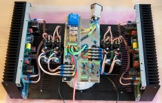
Very nice work, George, neat and tidy. I see you have your own power supplies, and these use 35A block rectifiers, which are not as good as the Philips BYV32Es I specced. However, it will still sound marvellous.....
I have a distortion profile, simulated, at 1KHz sine into 8R. It is instructive, because although the THD is 0.024%, quite high in my experience, it's mostly second and third harmonic. 7th is highish, -91dB, but 5th, a bothersome artefact, is -102dB. These are very good results and account, in my view, for the very engaging, natural sound.
Cheers,
Hugh
Attachments
Last edited:
Hugh,
This distortion profile looks good to me. THD is not only thing that is important in good sounding amplifier.
George
This distortion profile looks good to me. THD is not only thing that is important in good sounding amplifier.
George
also for those looking for mosfets , i bought mine here 2SK1058 2SJ162 Audio Power Mosfets - Buy Online @ AmpsLab[/QUOTE]
Thank you for this information!
Thank you for this information!
- Status
- Not open for further replies.
- Home
- More Vendors...
- AKSA
- Swordfishy/ASPEN FETZILLA power amp