It doesn't do upwards voltage translation and has negligible fan-out, both of which are important for the OPHEF4049 CMOS 15ns at 12 volts.
Shouldn't all these MCU manufacturers make them CMOS compatible so you can plug it in at any voltage, 5V, 10V, 15V ? Imagine an MCU with 8 input and 8 output pins, 16 pins in total which you must somehow translate to different voltages. Plus the lack of a good quality on board DAC. I am new to MCUs only just started with a Nano (Atmega328p)
How much Power is dissipated in the switching transistor DURING the switch off period?
Proportional to the time it takes it to come out of saturation and switch off, I presume, so the shorter the better? Also, if we do not switch it on fully we will be spending power while it is on, not a good thing.
On another note I received today the CD4504BE and it is fantastic, it is everything you'd expect in a tight package, superb on and off times, and very sharp squares. The bad news is the current capability, which at 12V shows immediately with a single LED at 5mA as the "on" voltage drops - it is only specified to 2.6mA at 10V, so pulling 5mA at 12V is pushing it.
I also received a bunch of MPS2222A and they are faster to switch off than the BC550C, but still in us rather than ns. The speed up capacitor of course helps and it even helps with the CD4504BE as I tested.
time to switch off must be short enough that the heating effect does not overload a low Pmax device.
I looked up the digital circuit family used to build the CDC 6600 supercomputer in 1964; they called it "DCTL" (direct coupled transistor logic) and built it out of 2N2369A discrete NPN transistors. Here is the textbook, see Figures 12-15 (p.22-24) {warning: large .pdf!}. As you can see, they claimed that DCTL gates have an average switching time of 5 nanoseconds.
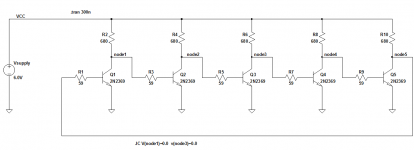
I built a 5 stage ring oscillator out of DCTL gates and simulated it in LTSPICE, schematic attached. The simulated oscillation frequency was 19.7 MHz (using the 2N2369 .MODEL provided by Linear Technology). Thus a complete period of oscillation requires 50.8 nanoseconds. There are five transistor switch-on events, and five transistor switch-off events, in each 50.8 nsec period. They're switching on and off pretty doggone fast.
The oscillation period of a 5 stage ring oscillator is 10 gate delays (5 gate delays for the high-time, and 5 gate delays for the low-time). So the average gate delay in simulation was (50.8 nsec / 10 gates) = 5.08 nsec/gate. Just as the CDC guys designed it, fifty years ago. Hats off to you, gentlemen.
A couple of fun facts: the complete CDC 6600 computer system contained 400,000 NPN transistors (p.20) and its mean time between failures due to transistor failures alone, was "over 2000 hours". About 3 months if you're running 24 by 7. Gulp!
Attachments
Have they chosen the base resistor and collector resistor values to give good enough unambiguous switching voltages and yet hold the switches just far enough out of hard saturation?
If this is their "trick", that might explain why they get fast switching times.
The low base resistor value will certainly help with low switching times.
If this is their "trick", that might explain why they get fast switching times.
The low base resistor value will certainly help with low switching times.
Now our CPUs have > 1billion switches and go on for years, sometimes continuously, without an apparent failure.A couple of fun facts: the complete CDC 6600 computer system contained 400,000 NPN transistors (p.20) and its mean time between failures due to transistor failures alone, was "over 2000 hours". About 3 months if you're running 24 by 7. Gulp!
Have they chosen the base resistor and collector resistor values to give good enough unambiguous switching voltages and yet hold the switches just far enough out of hard saturation?
If this is their "trick", that might explain why they get fast switching times.
The low base resistor value will certainly help with low switching times.
Yes it seems obvious and I have read that they needed a collector current enough to power up to 5 or 6 similar devices, and they had a hfe=10. If you read the book it mentions what I knew as a rumour, the longest piece of wire was like 2-3 inches because they had measured propagation delay in ns per foot. Things were so hot the computer had a dedicated freon cooling system. They were amongst the first to use silicon transistors which could handle more Ic, more power, ran cooler and more reliably than germanium. Very good read.
... and they had a hfe=10.
Not quite. The table you are referring to, shows the chosen Ic/Ib ratio in saturation. CDC selected a ratio of 10, which gives a good balance between low Vce_sat and fast base-region carrier sweepout. Most transistor data sheets (both ancient and modern) measure Vce_sat at an Ic/Ib ratio of 10, for the same reason. Look at a few and see for yourself.
Vacuum tube digital logic gate afficianados may recognize one of their OLD speedup tricks, in the plot of gate output voltage vs time. But in this transistorized version, the speedup diodes come for free as part of the preceding and following gates. You will note that Fairchild's uA914 IC digital logic family, which used a superficially very similar schematic, deliberately avoided this stunt. Fairchild chose slower and safer. They weren't building the worlds fastest computer.
Not quite. The table you are referring to, shows the chosen Ic/Ib ratio in saturation.
Is there a state other than saturation that determines their choice of Rb?
Ic/Ib ratios can be from 1:1 to 20:1 and probably outside that range.
As the ratio goes closer to 1:1, the turn off will get slower.
As the ratio goes closer to 1:1, the turn off will get slower.
All it takes to find out is (i) a transistor model; (ii) a circuit schematic; (iii) a simulator program; (iv) enthusiastic, fervent determination; (v) willingness to spend time performing experiments and studying results.Is there a state other than saturation that determines their choice of Rb?
- Status
- Not open for further replies.
- Home
- Amplifiers
- Power Supplies
- Switching a transistor off