Hello
This is a general question. I have an NPN transistor used as a switch. Emitter is either grounded or has some small resistance to prevent large base currents. Anyway. I can switch this transistor on very fast, I see 40ns on the scope, even less.
However to switch it off takes 2-10us, that is 2,000-10,000 ns.
A lower base resistance helps up to a point (because we are then loading the source).
Is there a simple transistor configuration to replace/augment the simple NPN switch so it can be switched off quicker?
Thanks
The simplest solution is to use a MOS (or a jFET).Is there a simple transistor configuration to replace/augment the simple NPN switch so it can be switched off quicker?
Otherwise, make a search with the terms: "storage time", "speed-up capacitor" and "Baker clamp"
Hi
I replaced the BC550C with a BS170 (MOSFET). The BS170 almost halved the switch off time, but unfortunately also increased the on time 6 fold...
A jFET requires good amounts of negative voltage to switch it off.
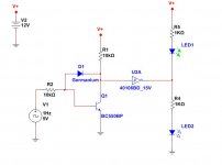
I then tried the "baker clamp" with a BAT48 Schottky and it provided no benefits. As a last resort I used a germanium diode OA47 and it did the trick! Amazing. The diode does nothing for the on times, but it halved or more the off time.
Thank you Elvee.
Now this was all part of my research into converting the digital output of an MCU, 0-5V, to 0-Vcc (eg 12V) as exists on some other analgue circuit, and it must both source and sink (that is important). My solutions included
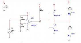
1) LM293 comparator (open collector output) followed by a push/pull transistor stage (so it can source and sink)
2) regular op-amp wired as a comparator (as long as the op-amp can accept 0V input)
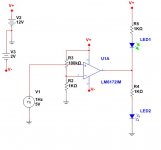
3) ultra fast op-amp (eg LM6172 or LT1361)
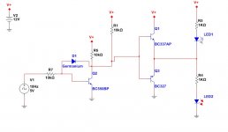
4) NPN transistor feeding an inverter Schmitt trigger CD40106BE
5) NPN transistor followed by transistor push-pull like the comparator
And the results
1) ultra fast op-amps have absolute best on times but terrible off times. LM6172/LT1361
2) average fast op-amps have fast on and off times TLE2142
3) normal op-amps have slow on times and average off times MC33072
4) Comparator + push-pull transistors have fast on and off times
5) NPN transistor + push-pull (3 transistors in total) have fast on and off times
6) NPN transistor + inverter CD40106 have fast on and off times
In terms of pin count and simplicity a moderately fast op-amp seems to win. But it is expensive (TLE2142 is like £2.00 each). If the fast on and off times are not needed then a normal op-amp is fine (MC33072 costs 50p). If we need the speed, the next best would be NPN+CD40106 (hex inverter) or comparator + pull pull transistors.
Am I correct in my analysis here or am I missing something obvious?
I replaced the BC550C with a BS170 (MOSFET). The BS170 almost halved the switch off time, but unfortunately also increased the on time 6 fold...
A jFET requires good amounts of negative voltage to switch it off.
I then tried the "baker clamp" with a BAT48 Schottky and it provided no benefits. As a last resort I used a germanium diode OA47 and it did the trick! Amazing. The diode does nothing for the on times, but it halved or more the off time.
Thank you Elvee.
Now this was all part of my research into converting the digital output of an MCU, 0-5V, to 0-Vcc (eg 12V) as exists on some other analgue circuit, and it must both source and sink (that is important). My solutions included
1) LM293 comparator (open collector output) followed by a push/pull transistor stage (so it can source and sink)
2) regular op-amp wired as a comparator (as long as the op-amp can accept 0V input)
3) ultra fast op-amp (eg LM6172 or LT1361)
4) NPN transistor feeding an inverter Schmitt trigger CD40106BE
5) NPN transistor followed by transistor push-pull like the comparator
And the results
1) ultra fast op-amps have absolute best on times but terrible off times. LM6172/LT1361
2) average fast op-amps have fast on and off times TLE2142
3) normal op-amps have slow on times and average off times MC33072
4) Comparator + push-pull transistors have fast on and off times
5) NPN transistor + push-pull (3 transistors in total) have fast on and off times
6) NPN transistor + inverter CD40106 have fast on and off times
In terms of pin count and simplicity a moderately fast op-amp seems to win. But it is expensive (TLE2142 is like £2.00 each). If the fast on and off times are not needed then a normal op-amp is fine (MC33072 costs 50p). If we need the speed, the next best would be NPN+CD40106 (hex inverter) or comparator + pull pull transistors.
Am I correct in my analysis here or am I missing something obvious?
Why not use a CD4504B ? Or a HCF4504B (probably faster).
Mona
1) I did not know about it
2) very low source and sink current (2.8mA at 25C). For comparison the 555 sources and sinks 200mA! An average op-amp sources and sinks 20-30mA.
Hello
This is a general question. I have an NPN transistor used as a switch. Emitter is either grounded or has some small resistance to prevent large base currents. Anyway. I can switch this transistor on very fast, I see 40ns on the scope, even less.However to switch it off takes 2-10us, that is 2,000-10,000 ns. Is there a simple transistor configuration to replace/augment the simple NPN switch so it can be switched off quicker?
You could try pulling the base negative by 3 or 4 volts; however, it's best to directly ground the emitter and use a small base resistor instead.
Somewhere around several kOhms should be good, just small enough to guarantee saturation under worst case conditions.
A 2N4401 can switch on/off very fast.
Last edited:
With Elvee's suggestion, the "baker clamp", adding a germanium resistor between base and collector fixes the problem nicely. A low base resistor also helps but loads the driver. I will buy a few 2N4401 to try them out.
The turn-off times you listed are quite bad for such a small bjt.
So I think you spoil turn-off switching by overdriving the bjt during on-time.
You could achieve great improvements by using an "unsatured" configuration, i.e. the collector-emitter voltage never drops below let us say one volt.
All these things depend on your test circuit, so I think you should post a sketch of your test setup.
Try the 74F06 integrated circuit. It's got an open collector output {in fact, six of them in the same IC package} and turn-off delay is 6.5 nanoseconds max, 3.5 nanoseconds typical. Here is the datasheet
Each 74F06 collector will pull 64 milliamps and will withstand 12 volts. If you need more current just put several gates in parallel; being open-collector, they can't possibly fight one another.
Seymour Cray used the PN2369A in the CDC-6600 supercomputer; yes, they really did build an entire computer out of discrete transistors (!). It's a gold doped, super high speed switching transistor, meant to be operated in the saturation region with (Ic/Ib) = 10. But CDC's computers didn't use TO-92 (plastic) packages; oh no. They use TO-18 hermetically sealed metal packages, and those parts were 2N2369As, not PN2369As.
Protip: LTSPICE ships with a presupplied .MODEL of a 2N2369 transistor.
Last edited:
The turn-off times you listed are quite bad for such a small bjt.
So I think you spoil turn-off switching by overdriving the bjt during on-time.
You could achieve great improvements by using an "unsatured" configuration, i.e. the collector-emitter voltage never drops below let us say one volt.
All these things depend on your test circuit, so I think you should post a sketch of your test setup.
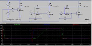
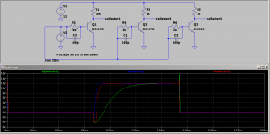
OK here are all the individual tests as I have them on the breadboard.
Attachments
Try the 74F06 integrated circuit. It's got an open collector output {in fact, six of them in the same IC package} and turn-off delay is 6.5 nanoseconds max, 3.5 nanoseconds typical. Here is the datasheet
Each 74F06 collector will pull 64 milliamps and will withstand 12 volts. If you need more current just put several gates in parallel; being open-collector, they can't possibly fight one another.
Seymour Cray used the PN2369A in the CDC-6600 supercomputer; yes, they really did build an entire computer out of discrete transistors (!). It's a gold doped, super high speed switching transistor, meant to be operated in the saturation region with (Ic/Ib) = 10. But CDC's computers didn't use TO-92 (plastic) packages; oh no. They use TO-18 hermetically sealed metal packages, and those parts were 2N2369As, not PN2369As.
Protip: LTSPICE ships with a presupplied .MODEL of a 2N2369 transistor.
I need a source/sink capability system and the open collector is just like a comparator - you have to bolt on to it additional transistors to allow it to source current too.
The 2N2369A is interesting, suggests turn off times of 15ns out of saturation!! But it costs a bomb 🙂
I have read now based on Elvee's links, and it seems I have hit upon a textbook problem. But it only becomes a problem if you are into high frequencies or speeds. In my case it is academic , I just saw it on the scope and started wondering. I realised it is saturation related, a problem I hit upon before with amplifier output drivers at high frequencies, but I did not know how to cure it other than lowering the base resistor, which unfortunately then places big demands on the driver.
I will send you 10 pieces of PN2369A, I bought them for USD 11 per 100 pieces when Clinton was President. But they are only as hermetic as epoxy packaged semiconductors. If you are a purchasing agent for Space-X, and you need seven-nines reliability at -55C AND 100% humidity, look elsewhere
Yes I had checked 2N2369 in this sim as well with the values used by variant3, but there was only little improvement. So I removed variant4.
Last edited:
next better solution....
BTW, there are comparators available with source/sink, that is, a push pull output stage.
Using the 393 comparator, you can also use a smaller value of pull down resistor to speed things up, as low as 600 Ohms for a 12V supply.
Last edited:
BTW, there are comparators available with source/sink, that is, a push pull output stage.
Using the 393 comparator, you can also use a smaller value of pull down resistor to speed things up, as low as 600 Ohms for a 12V supply.
The LM393 requires a pull up resistor😉
next better solution....
My own tests with oscilloscope differ in that the switch off times are in the region of us, not fractions of us. The on times are also a bit slower maybe 30-40ns. The breadboard may have some parasitic capacitances contributing to slightly elevated results but not by that much.
I actually did a search and landed on "http://electronics.stackexchange.com/questions/23349/what-is-wrong-here-a-simple-npn-switch"
where the guy reports "almost 2us to switch off". These are my findings too for 10K base and collector resistors and no speed-up capacitors or diodes.
Here are the numbers:
NPN BC550C
transistor with 10K base and collector:
on: 240ns
off: 2500ns
transistor with 10K base and collector and OA47 germanium diode:
on: 250ns
off: 1100ns (but 0V is now 200mV).
transistor with 10K base and collector and 1N4148 diode:
on: 250ns
off: 1200ns
transistor with 10K base and collector and OA47 germanium diode and 100pF cap:
on : 18ns and a bit of a bounce making it 30ns
off : 750ns-850ns
Actually once the cap is in, the diode makes little difference. The germanium is best for time but due to its speed and/or leakage it does not let the Vce drop enough so we get a couple of 100 mV instead of 0V. There are low-leakage germanium diodes on ebay, apparently (eg 1N34A if we are to believe they are genuine)
****************************************
In terms of voltage shifting I believe the solution should be entirely integrated otherwise the board will be strewn with loose transistors (and caps and diodes) - there should be an IC like the CD40106 hex inverter (which produces very nice and square traces) or the CD4504 but with higher current capability so we do not need extra components. Or even a comparator with push-pull at the output - there are very few at >= 12V, I am looking now, I will buy a few to see if they beat the op-amps (I do not think they will since the push-pull output means inability to reach the rails).
That is why I favoured the moderately fast op-amp solution, because it does not need extra components, unfortunately it is not rail-to-rail, so for true 0V you will need to feed it a -2V, and you will never get true +Vcc, however even the 555 achieves 1.3V off the rail.
Use MOS drivers: they exist in many varieties, they sink and source currents >1A, they switch in tens of ns at most, they exist in dual, quad, etc and they take care of the voltage translation.In terms of voltage shifting I believe the solution should be entirely integrated otherwise the board will be strewn with loose transistors (and caps and diodes) - there should be an IC like the CD40106 hex inverter (which produces very nice and square traces) or the CD4504 but with higher current capability so we do not need extra components.
Examples from Microchip (all founders have them):
Power MOSFET Drivers Products - Microchip Technology Inc
http://ww1.microchip.com/downloads/en/DeviceDoc/21425C.pdf
- Status
- Not open for further replies.
- Home
- Amplifiers
- Power Supplies
- Switching a transistor off