This is my DIY project of a modular stereo line array. A bit unconventional because I fastened monitors to the face of a solid pole instead of installing ribbons/woofers inside a hollow column. This simple thinking-outside-the-box [line array pun #1] came from wanting to get close to a live-concert-size (er, should I just say larger-than-life sized…?) feel from the Anthony Gallo Acoustics speakers I like. No matter how loudly I might play a pair, the most recent iteration of “reference” model - Strada 2 - just wasn’t going to feel like a performance hall in my living room. Not surprised. I had no interest in the sum it would cost to import an ol’ used pair of Gallo 5LS’s, and even less interest in the sum such acquired-taste-lookin’ “silver sentinel” speakers would cost my relationship… in a Hong Kong apartment!
I wanted line array performance that could be readily packed away out of sight when not in use. No small feat given the HK apartment constraints (“What’s a garage!?” … “Oh, it’s like closets, and unicorns - pure fiction, I assure you!”). I also wanted the setup to ship with relative ease, if need be. Mine would seem an impossibly tall order [line array pun #2].
Thinking how the 5LS was essentially [on the front] four replicates of the AGA Reference 3.1 top half, with extra CDT’s in between, I began to wonder how such an approach with Stradas - the top half of the well-touted Ref 3.5, might sound. But by then, I needed to use the most recent iteration (Strada 2, with a significantly higher “natural” crossover between woofers and CDT than the original (pre-2012) Strada found on said Ref 3.5, which meant even more technical difference from the 5LS layout. Baby steps needed.
What started in (I think) 2018 as two pairs of Strada 2’s wired parallel on test bench-looking lumber…

…has evolved into a setup today that, with a handheld screwdriver, step ladder, and 45 to 50 minutes, I can take down and pack away out of sight.

Hedge all excitement, because the frequency response has not been tested. Even if I used DSP or other treatments, I’m skeptical of a truly flat result given certain features of the room.
Despite possible/likely issues, the human listener response has been positively awestruck in literally every case, so far. Even visitors from whom I expected snide remarks based solely on appearance of the setup, have thrown around the term “perfect” without hesitation. While perfection is surely not reality here, I’m impressed how no one but me has perceived any shortcomings of this setup, yet.
Yes, the subwoofers are needed a bit below 100 Hz, and are not fully resolved as there’s obvious dropout past a certain point in the long room - I suspect a point source bass problem. The line arrays receive full signal, no crossover other than what’s in each powered sub (Gallo Acoustics TR3-D), so I’m telling myself they’re technically full range speakers 😉 and belong in this forum.
No, this project was obviously not cheap, but given it’s flexibility that no other non-PA line array likely offers, and can be built up over time vs. an all at once investment (more on that in subsequent posts if there’s interest), AND is less costly today than the 5LS was back in 2008, it seems a fine outcome based on the performance I hear. Might an entry-level Scaena show better behavior if tested in the same room? I’d expect so. But compare the price points and it’s no competition, for me.
I wanted line array performance that could be readily packed away out of sight when not in use. No small feat given the HK apartment constraints (“What’s a garage!?” … “Oh, it’s like closets, and unicorns - pure fiction, I assure you!”). I also wanted the setup to ship with relative ease, if need be. Mine would seem an impossibly tall order [line array pun #2].
Thinking how the 5LS was essentially [on the front] four replicates of the AGA Reference 3.1 top half, with extra CDT’s in between, I began to wonder how such an approach with Stradas - the top half of the well-touted Ref 3.5, might sound. But by then, I needed to use the most recent iteration (Strada 2, with a significantly higher “natural” crossover between woofers and CDT than the original (pre-2012) Strada found on said Ref 3.5, which meant even more technical difference from the 5LS layout. Baby steps needed.
What started in (I think) 2018 as two pairs of Strada 2’s wired parallel on test bench-looking lumber…
…has evolved into a setup today that, with a handheld screwdriver, step ladder, and 45 to 50 minutes, I can take down and pack away out of sight.
Hedge all excitement, because the frequency response has not been tested. Even if I used DSP or other treatments, I’m skeptical of a truly flat result given certain features of the room.
Despite possible/likely issues, the human listener response has been positively awestruck in literally every case, so far. Even visitors from whom I expected snide remarks based solely on appearance of the setup, have thrown around the term “perfect” without hesitation. While perfection is surely not reality here, I’m impressed how no one but me has perceived any shortcomings of this setup, yet.
Yes, the subwoofers are needed a bit below 100 Hz, and are not fully resolved as there’s obvious dropout past a certain point in the long room - I suspect a point source bass problem. The line arrays receive full signal, no crossover other than what’s in each powered sub (Gallo Acoustics TR3-D), so I’m telling myself they’re technically full range speakers 😉 and belong in this forum.
No, this project was obviously not cheap, but given it’s flexibility that no other non-PA line array likely offers, and can be built up over time vs. an all at once investment (more on that in subsequent posts if there’s interest), AND is less costly today than the 5LS was back in 2008, it seems a fine outcome based on the performance I hear. Might an entry-level Scaena show better behavior if tested in the same room? I’d expect so. But compare the price points and it’s no competition, for me.

So, that's 12x 4' woofers and 6x tweeters per line?
I suspect the drops you are experiencing is from comb filtering, something every line array suffers from. Usually, reducing the c-to-c between each driver is the best solution, but I see in this case that will be impossible.
They do look cool, and as long as you are happy with the end result, and it fits your requirements, then all is good.
You actually have quite a big living room, comparing to HK's averaged sized rooms!
The bass issue might be because you are sending it to both the line arrays and the subs.This is my DIY project of a modular stereo line array. A bit unconventional because I fastened monitors to the face of a solid pole instead of installing ribbons/woofers inside a hollow column. This simple thinking-outside-the-box [line array pun #1] came from wanting to get close to a live-concert-size (er, should I just say larger-than-life sized…?) feel from the Anthony Gallo Acoustics speakers I like. No matter how loudly I might play a pair, the most recent iteration of “reference” model - Strada 2 - just wasn’t going to feel like a performance hall in my living room. Not surprised. I had no interest in the sum it would cost to import an ol’ used pair of Gallo 5LS’s, and even less interest in the sum such acquired-taste-lookin’ “silver sentinel” speakers would cost my relationship… in a Hong Kong apartment!
I wanted line array performance that could be readily packed away out of sight when not in use. No small feat given the HK apartment constraints (“What’s a garage!?” … “Oh, it’s like closets, and unicorns - pure fiction, I assure you!”). I also wanted the setup to ship with relative ease, if need be. Mine would seem an impossibly tall order [line array pun #2].
Thinking how the 5LS was essentially [on the front] four replicates of the AGA Reference 3.1 top half, with extra CDT’s in between, I began to wonder how such an approach with Stradas - the top half of the well-touted Ref 3.5, might sound. But by then, I needed to use the most recent iteration (Strada 2, with a significantly higher “natural” crossover between woofers and CDT than the original (pre-2012) Strada found on said Ref 3.5, which meant even more technical difference from the 5LS layout. Baby steps needed.
What started in (I think) 2018 as two pairs of Strada 2’s wired parallel on test bench-looking lumber…
View attachment 1050851
…has evolved into a setup today that, with a handheld screwdriver, step ladder, and 45 to 50 minutes, I can take down and pack away out of sight.
View attachment 1050841
Hedge all excitement, because the frequency response has not been tested. Even if I used DSP or other treatments, I’m skeptical of a truly flat result given certain features of the room.
Despite possible/likely issues, the human listener response has been positively awestruck in literally every case, so far. Even visitors from whom I expected snide remarks based solely on appearance of the setup, have thrown around the term “perfect” without hesitation. While perfection is surely not reality here, I’m impressed how no one but me has perceived any shortcomings of this setup, yet.
Yes, the subwoofers are needed a bit below 100 Hz, and are not fully resolved as there’s obvious dropout past a certain point in the long room - I suspect a point source bass problem. The line arrays receive full signal, no crossover other than what’s in each powered sub (Gallo Acoustics TR3-D), so I’m telling myself they’re technically full range speakers 😉 and belong in this forum.
No, this project was obviously not cheap, but given it’s flexibility that no other non-PA line array likely offers, and can be built up over time vs. an all at once investment (more on that in subsequent posts if there’s interest), AND is less costly today than the 5LS was back in 2008, it seems a fine outcome based on the performance I hear. Might an entry-level Scaena show better behavior if tested in the same room? I’d expect so. But compare the price points and it’s no competition, for me.
Try using a HPF to remove the bass from the line arrays and try to position the subs directly under the line arrays (but decoupled so the subs don’t shake the line arrays) to get the phase correct.
I tested my line arrays in both configurations and they were noticeably better with the HPF.
Thanks for the feedback, perceval. Strange thing about the array is, only the CDT’s ( = “Cylindrical Diaphragm Tweeter” - basically short, curved ribbons) have inherent spacing issues in this setup, but the highs are not the drop culprit [seemingly].So, that's 12x 4' woofers and 6x tweeters per line?
I suspect the drops you are experiencing is from comb filtering, something every line array suffers from. Usually, reducing the c-to-c between each driver is the best solution, but I see in this case that will be impossible.
They do look cool, and as long as you are happy with the end result, and it fits your requirements, then all is good.
You actually have quite a big living room, comparing to HK's averaged sized rooms!
I made sure to get each monitor spaced exactly, according to how the woofer/sphere design on either side of each monitor’s CDT is arranged - 3.5” needed between each 5” diameter steel sphere.
I did make the mistake of not using that spacing between spheres of adjacent monitors in an earlier (x8 woofer) version:
Again, that is not the way these monitors should be spaced!
The 12x 4” woofers in the present version at least sound like [*subjectivity alert, subjectivity alert*] they’re coupling properly, as the individual monitor’s paired woofer design must intend. Within ~4’ or less of the speakers, it should be possible to hear gaps in the CDT’s bandwidth if you move up and down - if vertical dispersion is indeed 30°, there have to be gaps in the extreme near field. Gaps, not combing. I would expect combing of the CDT’s frequencies further back in the room. That’s perhaps even stranger - combing must surely be occurring, especially with the CDT’s 180° dispersion in the horizontal plane (and here, towards two mostly exposed concrete walls). But, I really can’t pick up on combing anywhere in the room. I expect waveform measurements of even the sort a phone app performs could expose some nasty spots, but then we circle back to how my ears aren’t picking up on it… so do I really want to sac’ my blissful ignorance for a handful of graphs, lol!? Because you’re right about something I knew well when I opted to add more than a second monitor per channel - there’s no adjusting the c-to-c spacing in this setup for tweeters. The 5LS added several extra tweeters per channel instead of the blank spots I have between monitors. The AGA company stated the 5LS CDT’s had their vertical dispersion attenuated to prevent combing, but never mentioned what the angle of attenuation was. Necessarily, there was either a “sweet spot” where everything intersected perfectly, and behind which much combed, or there were gaps in the highs depending on listeners’ distance from the speakers and/or height. Those probable inconsistencies are no real issue with mine, thankfully. They’re nearly 9’ tall and meant for folks standing or on bar stools, or laying on the floor after too many 😉. These speakers have issues, but defying the single “sweet spot” is not among them.
The drop is in the bass, past ~18’ from the subs. That conforms to what would be expected of decibel drop in primary waves around 100 Hz coming from single woofers, and it is probably exacerbated by the wide, deep, high bar that separates the living room from the open kitchen at the same distance. Between the speakers and the bar (living room), everything aligns well. Opposite side of the bar (kitchen), everything but what the subs produce remains pretty much the same. Again, based on human listening only - no analyses yet.
Glad you like the way they look. They’d blend with a dark pole better, but the raw wood tone polled to be more appealing for how it unified the floor/ceiling. Your positive attitude of if-you’re-happy-with-it is great. And you’re also right re: apartment size. I am absurdly lucky, especially by HK standards. Last apartment where this idea began was small, and layout of the living room was simply not up to modern standards for anything, let alone entertaining or listening. My current residence readily converts into a “huge” entertaining / listening room.
The bass issue might be because you are sending it to both the line arrays and the subs.
Try using a HPF to remove the bass from the line arrays and try to position the subs directly under the line arrays (but decoupled so the subs don’t shake the line arrays) to get the phase correct.
I tested my line arrays in both configurations and they were noticeably better with the HPF.
That’s a good suggestion. Thank you.
Funny enough, my initial setup of these monitors was one L/R pair, and the pair of subs. I ran the L/R monitors through the L/R HPFs on the subs, with subs directly behind the MLP (couch in middle of room) and adjusted to account for [reverse] phase and room modes. The bass was fine for the space, but the monitors sounded, well, lackluster. Wasn’t sure if the culprit was speaker positioning, way too much speaker wire, the HPFs, or all the above, so I tried revising each factor. I ultimately moved the subs directly under the monitors and also removed the monitors from the HPFs; all was better (wire length had little effect from what I could tell). Another person shared a similar experience in his HT setup on the Gallo AVS thread some months back. Gallo HQ told him to connect the monitors directly to the receiver terminals. It seems the Strada really prefers to run full range.
Sssooo, I never considered HPFs again, but maybe I should have - after all, what I’m running now is a bit of a departure from the typical sub-statt setup! For sake of curiosity, I’ll aim to run the monitor arrays from the subs’ HPFs this weekend.
On my bass issue, I should’ve been more specific - indeed it’s no problem at all until you get far enough back (~18’) where certain lower wavelengths [should] begin to demonstrate decibel drop.
I’m not excited about the notion of adding more subs. They’re not cheap, and they won’t store easily. The current pair of subs pulls double duty as the low-end for my tv speakers (L/R A’Diva SE) by sitting on each side of the couch, when the arrays are off and/or down.
But, sigh, it seems like if I want to achieve similar effect in “upper bass” from the subs that I have with frequencies from the arrays, I’ll need to add at least one more pair. The 5LS I modeled parts of this project on tackled bass with a column of 12 4” LPF woofers down the backside. So the surface area of the 5LS’s 4” LPF woofer column is 2x that of the 10” sub. If I hold Gallo’s surface area proportions more or less constant in my scenario, I need 3 subs… per channel, as things now stand.
Unfortunately, re: subs directly under the arrays, I won’t, and I can’t. Won’t because it’d require me to delete the bottom monitors (and thus also the top monitors - impedance to consider), separating the array from floor/ceiling boundary spacing and potentially disrupting reflective behavior? Can’t for the same reason, and also because I have to keep the subs off the floor - they excite the concrete building no matter what kind of isolators I use. Although I can position the subs on the floor and alter their settings to correct for modes in my living room, it would still seem merciless to the families living in the reverb chambers below my apartment 😅
I pushed the subs 2’ behind the arrays because that’s how TR3-D’s were shown with Stradas by AGA at past expos. I’ll bring in a couple of low stools to move the subs forward - that’d gain me at least 2’ from the wall. I’ll follow up after I try that and the HPFs. Admittedly curious!
You are right, the bass issue at distance could be the different rate of drop off of the line array and point source — it isn’t possible to match them perfectly everywhere.
It might be the HPF is the right idea but the one in the sub isn’t good enough. I don’t know what’s in your subs so it may very well be OK, but what you want is a high quality active crossover on the line level signal and then separate amps for the subs and line arrays.
I’m running mine from a couple of car stereos from a scrapyard (£5 each!). The head unit has an active crossover and I use the front channel for the line arrays and send the sub output to the aux-in of a second car stereo and use that for the subs. I have a head unit with a 3 way crossover so I could bi-amp the midrange and tweeters but the tweeters are currently inductively driven from the midrange so I’m not using that feature. I’m also only using two of the four available sub channels.
This is maybe not the audiophile quality you are interested in but it’s certainly a cheap way to prototype different ideas before investing in any final kit.
The shaking from a sub comes from the oscillating mass of the coil and cone and the force required to move the air. Some good subs contain two drivers in opposition so all the forces balance and cancel out. This almost eliminates the energy transferred into the sub enclosure (and from there to the floor). The remaining energy comes from movement in the enclosure driven by the internal pressure change (like a balloon being inflated and deflated). With a pair of enclosures in opposition, this movement has a stationary node in the middle where the two enclosures are connected together (the necks of the balloons connected together) so that is a good place to support the pair of enclosures with a floor stand as it will minimize the coupling to the floor.
In my line array, I made 4 subs and put them in pairs firing vertically in opposition for perfect balance. So they squeeze the bass out radially from the vertical gap between them. I’m not sure what the optimal gap is but I think as long as it is significantly smaller than the shortest wavelength of the bass frequencies then it’s probably not that critical. I’m not currently supporting mine from the stationary node in the middle as I should be; they are standing on the end of the bottom enclosure — so there is a little energy going into the floor but they are on carpet so it’s not a significant problem. I did previously have them suspended from the stationary node in the middle (hanging under the line array from a ceiling beam) and the bass is definitely better that way: the decay is more immediate so the bass is tighter and more accurate.
So, if you are looking for more ideas to try, you could try mounting your subs to fire vertically in opposing pairs, supporting them from the middle of the new connection between them.
You could also possibly try mounting the drivers of your line array in pairs in a V shape (maybe adjustable from narrow angle up to 180). This would halve the height of your line arrays which might be enough to make room for the vertically firing subs underneath. As long as the array extends vertically over the region where your ears will be, the treble should still be OK. I’m not so confident about this idea because line arrays have side lobes and the lobes of the two arrays in the V might interfere and impact clarity but, if I had your kit and a large room like yours I’d definitely try it out. You might be able to adjust the angle of the V to eliminate any problem from the side lobes.
With a rectangular array of half the height, there will be a little more vertical dispersion and I guess the image will shrink a bit but this may very well be from significantly larger than life to a more realistic life size so that may be a good thing. With my relatively short line arrays, the image still seems to be life size or larger.
You have nice kit to play with 🙂 have fun.
Last edited:
While that may seem true intuitively, in reality the (almost floor to ceiling) taller array will have a wider vertical pattern.With a rectangular array of half the height, there will be a little more vertical dispersion and I guess the image will shrink a bit but this may very well be from significantly larger than life to a more realistic life size so that may be a good thing. With my relatively short line arrays, the image still seems to be life size or larger.
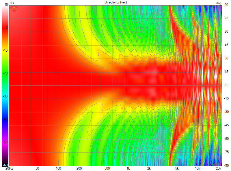
25 driver line array (because I had it on hand)
Versus the shorter:
15 driver line array
Both without any filters, running full range, no floor or ceiling effects added in this picture...
Line arrays behave pretty weird and not all that intuitive.... placing another row beside the 15 driver array isn't going to influence it's vertical output though.
An even shorter array of 10 drivers will exhibit an even smaller vertical beam:
10 driver line array by cutting off the 5 lowest drivers.
See how a shorter array has less vertical dispersion?
One thing I have learned playing with arrays for quite a while... don't assume, measure it... it isn't all that intuitive.
While I didn't measure it in this case, I do hope this quick and dirty simulation is accepted as an example of
vertical dispersion of arrays as a function of it's length...
I think you have to include the floor and ceiling effects when considering the difference between an array which actually extends from the floor to the ceiling and a shorter array that doesn’t. I think the floor to ceiling array has no vertical dispersion in theory and the shorter one has more. I may be wrong. In any case, I’m pretty sure the floor and ceiling are going to dominate the results.While that may seem true intuitively, in reality the (almost floor to ceiling) taller array will have a wider vertical pattern.
View attachment 1051494
25 driver line array (because I had it on hand)
Versus the shorter:
View attachment 1051495
15 driver line array
Both without any filters, running full range, no floor or ceiling effects added in this picture...
Line arrays behave pretty weird and not all that intuitive.... placing another row beside the 15 driver array isn't going to influence it's vertical output though.
An even shorter array of 10 drivers will exhibit an even smaller vertical beam:
View attachment 1051498
10 driver line array by cutting off the 5 lowest drivers.
See how a shorter array has less vertical dispersion?
One thing I have learned playing with arrays for quite a while... don't assume, measure it... it isn't all that intuitive.
While I didn't measure it in this case, I do hope this quick and dirty simulation is accepted as an example of
vertical dispersion of arrays as a function of it's length...
I have and you'd be wrong in thinking that... 😉
My preference is for floor to ceiling arrays because of the floor and ceiling interaction. Not despite it. For a shorter array I'd use shading or a CBT array. For floor to ceiling I'm using frequency shading too, as I can optimize the vertical output that way. In other words: controll vertical beamwidth.
My preference is for floor to ceiling arrays because of the floor and ceiling interaction. Not despite it. For a shorter array I'd use shading or a CBT array. For floor to ceiling I'm using frequency shading too, as I can optimize the vertical output that way. In other words: controll vertical beamwidth.
Last edited:
Your post with the graphs specifically says that floor and ceiling interaction is not included. Is it or isn’t it?I have and you'd be wrong in thinking that... 😉
My preference is for floor to ceiling arrays because of the floor and ceiling interaction. Not despite it. For a shorter array I'd use shading or a CBT array. For floor to ceiling I'm using frequency shading too, as I can optimize the vertical output that way. In other words: controll vertical beamwidth.
If this were the only simulations I had ever done, you'd be right. But I've run dozens if not many more... short arrays, long arrays with and without floor and ceiling. Plus a world of array measurements to confirm the validity of the simulations.
My answer was based on those findings, but to present it in a likewise graph would require more work than I'm willing to do tonight.
My answer was based on those findings, but to present it in a likewise graph would require more work than I'm willing to do tonight.
So we are in agreement then that the graphs you posted are not relevant.If this were the only simulations I had ever done, you'd be right. But I've run dozens if not many more... short arrays, long arrays with and without floor and ceiling. Plus a world of array measurements to confirm the validity of the simulations.
My answer was based on those findings, but to present it in a likewise graph would require more work than I'm willing to do tonight.
No, we are not. As the point remains that the shorter array does not have a wider vertical sweet spot.
Not even with floor and ceiling reflections included. So the graphs do make my point more clear.
For those that can accept it, that is 😉.
Not even with floor and ceiling reflections included. So the graphs do make my point more clear.
For those that can accept it, that is 😉.
Well, I didn’t say it had a wider vertical sweet spot. I said it would probably have wider dispersion. Perhaps we don’t have the same understanding of that word.No, we are not. As the point remains that the shorter array does not have a wider vertical sweet spot.
Not even with floor and ceiling reflections included. So the graphs do make my point more clear.
For those that can accept it, that is 😉.
What would wider dispersion mean to you.... I already posted pictures what it means to me.
Wide:
25 driver array having a wide vertical sweet spot...
Narrow:
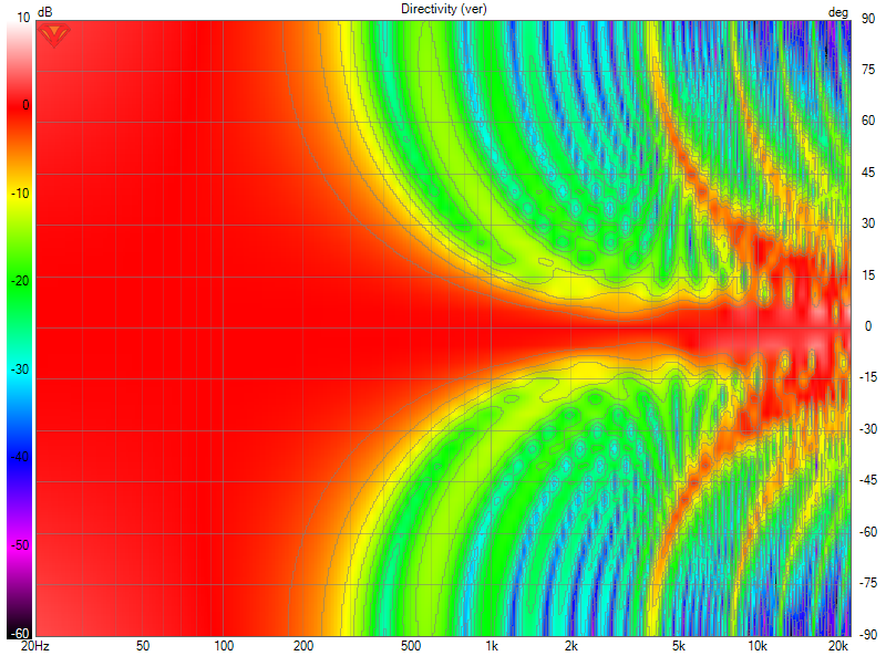
10 driver array having a more narrow sweet spot, hence more narrow dispersion.
And a single (3.5") driver having a wide dispersion:
.png")
Wide:
25 driver array having a wide vertical sweet spot...
Narrow:
10 driver array having a more narrow sweet spot, hence more narrow dispersion.
And a single (3.5") driver having a wide dispersion:
It seems that the word dispersion means to me the opposite of what it means to you.What would wider dispersion mean to you.... I already posted pictures what it means to me.
Wide:
25 driver array having a wide vertical sweet spot...
Narrow:
10 driver array having a more narrow sweet spot, hence more narrow dispersion.
comb filtering manifests itself, in this case, as a loss in high frequency .
Have you considered mounting the units in a stacked MTM configuration to reduce the average CTC distance (rather than end on end) . Might not be what you are looking , or it might
You could also play with the wiring connections and power taper them (units at the center wired for an effectively lower impedance / higher sensitivity ) than those at tye periphery of the line
Attachments
Last edited:
I believe the OP must have been inspired by Gallo's bigger speakers:
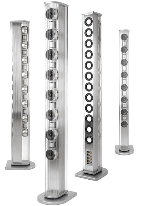
Or not... just a guess...
Or not... just a guess...
Good guess. Enter the AGA 5LS - yes indeed @wesayso. Btw - the “LS” stands for Line Source. Uses an older version of woofers and CDT’s, with their “natural crossover” ( = handover? ) being significantly lower than in the Strada 2 model I’m using. Wish oh wish I could replicate the project with original Strada’s to compare both versions in same room. Anyone have a dozen pre-2012 Strada’s to loan overseas? Oh, the worldly limitations working against scientific methodology!I believe the OP must have been inspired by Gallo's bigger speakers:
Or not... just a guess...
The empty part of the 5LS face at the bottom was by design, on purpose - Gallo perceived an issue with floor bounce of treble in normal rooms, and adjusted the height (~16” from floor) with the assumption of the same empty space above the speaker - i.e. designed for use under a typical 8’ ceiling.
I haven’t tried putting felt over my lowest/highest CDT’s yet, seems that would be better saved for after I run some preliminary tests (that whole test, change 1 variable, test again, groan, change 1 other variable, test again, groan again…) 😉 Might not achieve the same effect anyway, since woofers in older models shifted duty to CDT’s around 2,500 or 3,500 Hz; the Strada 2 woofers go up to ~6 kHz before CDT’s kick in, if my memory serves. Maybe not apples to oranges, but at least green apples to red apples, that comparison of older vs. newer.
- Home
- Loudspeakers
- Full Range
- Swingin’ on the Gallo’s Pole - a box-free modular line array