Works so far, resistor watt value in question.
It's the same as #35 except the switch.
I used a power strip and used that switch to feed the cord going to the breadboard.
I hooked up the relay, snaps closed and releases both very sharply🙂. I expected a delay on the relay re-opening, but the cap discharges quickly.
So I'm not sure that I really need the cap to be pre-charged as it functions just fine without it
I guess this is functioning good so far. But I have a concern about the resistor wattage....
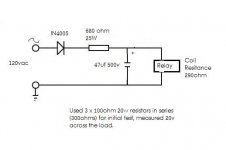
When I used the dropper speadsheet, a 120v supply would require a 649ohm resistor is series with the diode to produce 20v (6.5 watts). However, by using simple ohms law calculator, I would have to say that 680ohm across 170v would = 42.5 watts.
So, I think that spreadsheet is not right for this project since we added a cap to feed the voltage (and not as a capacitive dropper).
The single resistor gets HOT , and even tho it was disscussed to get the wattage match, I'd need a pretty good pile of resistors to get this all to match up.
I think I should shoot for a 50w (maybe ohmite?) or an aluminum heat-sink type. It would help keep the size of he installation small.
Draw what you have done and put all the voltages in 🙂 and just try it with the relay.
Is it like the circuit in post #35 ?
It's the same as #35 except the switch.
I used a power strip and used that switch to feed the cord going to the breadboard.
I hooked up the relay, snaps closed and releases both very sharply🙂. I expected a delay on the relay re-opening, but the cap discharges quickly.
So I'm not sure that I really need the cap to be pre-charged as it functions just fine without it
I guess this is functioning good so far. But I have a concern about the resistor wattage....
When I used the dropper speadsheet, a 120v supply would require a 649ohm resistor is series with the diode to produce 20v (6.5 watts). However, by using simple ohms law calculator, I would have to say that 680ohm across 170v would = 42.5 watts.
So, I think that spreadsheet is not right for this project since we added a cap to feed the voltage (and not as a capacitive dropper).
The single resistor gets HOT
, and even tho it was disscussed to get the wattage match, I'd need a pretty good pile of resistors to get this all to match up. I think I should shoot for a 50w (maybe ohmite?) or an aluminum heat-sink type. It would help keep the size of he installation small.
Attachments
You need the cap precharged.
Why ?
Because it allows the relay to snap shut at 170v, and then the resistor can be chosen to be much higher in value (ohms) as the relay will hold OK at a much reduced voltage. How low ? You are going to have to keep adding resistance to find out.
Do you see ? That's the whole point of doing it that way. To try and reduce the power dissipation.
ooooh. Ok I see. Quite right-If that's the case, then I can still test to a point this way to start with by just varying the resistance, since the whole thing will have to settle down anyway to a "holding" voltage.
I have a slight advantage it seems, since I have direct access to the contacts.
For example:
2k ohms : the contacts will not stay closed, even when the contacts are physically pushed down.
1.3k ohms : the contacts won't close on their own, but will hold when physically pushed down - (although this has a weak feel, like low power refrigerator magnet😱)
1.1K ohms : Again, no close, but a more powerful snap-closing on the assist. Also, I can actually hear the coil at this point humming just a little while it's open, as it is struggling to close, hum goes away when I assist the close.
So it looks like 1.1k is the current winner (although, there is still a little play room). Seems like good holding strength and I should be able to get the resistance and power dissipation with 2 resistors. Now it's a matter of picking up a switch for testing, so I can wire the cap(s) to be precharged and see if it will kick it closed.
After that, I'll try to use it to turn on the amp.
1 question, I wired a CL60 thermistor at the entrance before the diode during testing. I thought this might not be a bad idea to protect the diode, since it will always be connected to AC (+). Agree-disagree?
Last edited:
It's getting there then 🙂
Things to try... different value caps. I suggested 47uf. You can always try 68 or 100uf.
Also try adding a cap after the rectifier as well (so that's two caps) of similar value. That will reduce ripple further, it will also increase the "average" DC level a little so again experiment with resistors. A 1.2 or 1.5k may then be OK. You have to try all the possibilites, there is no right and wrong answer. It has to be the best compromise for the particular relay.
Thermistor... I don't really think that will do anything really. The whole circuit should be behind a fuse for good practice... maybe a separate low value fuse rather than the main one in the amp.
Components are rated for 24/7 operation when used correctly, and the diode is well withinn it's ratings. Fuse is good practice though, in case a cap failed etc.
Getting there...
wow....
Ok, with that first setup, 1.1kohms + 1 x 47uf cap, I get that nice "snap" closing that you were talking about. Allowing the cap to be charged, putting a switch after the cap.
Since I ordered 2 x 47uf caps, I took your advise and tried both together, putting 1 just after the diode/before the resistors, 1 after.
Well, this ends up being a whoooole different story-lol. As it stands, I've got 2.7kohms in the circuit (checked measurement) and still the relay will close on its own without even pre-charging the caps!!!
Looks like a better direction. I haven't reached the limit of resistance yet since I ran out of test resistors. But this is going to be a much higher overall resistance with much lower power dissipation, entering the 10watt range.
Actually, I see everything more clearly now. Even going back to 1 x 47uf cap alone, but placing it on the diode end, still functions as above with 2.7k, closing the relay-no pre-charge.
I think I got it...
1) I could keep it simple- with 1 cap on the diode side with a smidge lower resistance with slightly higher power dissipation (around 15 watts) or...
2) Use two caps- in the snap close arrangement with even more resistance yeilding lower power dissipation (10w or less)
Cool😎
I don't think I need different caps at this point, I did try a single 100uf but there isn't any clear advantage, the 47's are doing the job just fine. It would also be expensive to keep ordering high quality high voltage caps and continue to get gouged on the $hipping.
🙂 You see... experiment.
I think whatever set up you use, having a 47uf precharged that the relay can use will give you the highest (which is what you want) resistor.
It's not as easy to analyse as you might think... because there will be a significant ripple voltage too... but thats not a problem here.
Keep experimenting 😉
Trying it out
I moved to the amp and the whole circuit is now self supporting using the amps power and main power switch. Components are still on a breadboard though. (by the way I omitted the bleeder resistor, since the dropper resistance does this just fine when it's all unplugged)
As you suggested I did some more experimenting. I stuck with the cap/resistor/cap pre-charge. What I did was to allow the contacts to grip with an assist, where they hold a contact but without much force (ala-refrigerator magnet hold) just to push the limits.
Then I allowed the precharging to function, which of course snaps hard.
I ended up with 4k ohms.... amp turns on and everything seems to be working fine. So far so good. THANK YOU!
At wrap up I might go back up to 3k+, as that holds together a little tighter against the spring-force and gives me a warmer fuzzier feeling...
A few final thoughts: The resistors are still pretty darn hot . Right now I'm using 1k+1.5k+1.5k 25w ceramics. I wonder if I haven't considered something in the power dissipation - seems like I should be way safe on this.
Also, I would like to use 1 resistor only for a cleaner install. Ohmite has those smooth nice looking resistors. Can you make any suggestions?
Finally, I grabbed a 1N5406 3A/600v diode as I liked the heavy gauge leads, which looked a little more "solder friendly". Any thoughts on using those?
I moved to the amp and the whole circuit is now self supporting using the amps power and main power switch. Components are still on a breadboard though. (by the way I omitted the bleeder resistor, since the dropper resistance does this just fine when it's all unplugged)
As you suggested I did some more experimenting. I stuck with the cap/resistor/cap pre-charge. What I did was to allow the contacts to grip with an assist, where they hold a contact but without much force (ala-refrigerator magnet hold) just to push the limits.
Then I allowed the precharging to function, which of course snaps hard.
I ended up with 4k ohms.... amp turns on and everything seems to be working fine. So far so good. THANK YOU!
At wrap up I might go back up to 3k+, as that holds together a little tighter against the spring-force and gives me a warmer fuzzier feeling...
A few final thoughts: The resistors are still pretty darn hot
. Right now I'm using 1k+1.5k+1.5k 25w ceramics. I wonder if I haven't considered something in the power dissipation - seems like I should be way safe on this.Also, I would like to use 1 resistor only for a cleaner install. Ohmite has those smooth nice looking resistors. Can you make any suggestions?
Finally, I grabbed a 1N5406 3A/600v diode as I liked the heavy gauge leads, which looked a little more "solder friendly". Any thoughts on using those?
1N5406 diode is fine for 120 vac supply.
It sounds about as good as you are going to get it really. Only other options now are to look for a different relay... perhaps one with a DC rated coil rather than an AC one, with a view to getting one with a higher resistance, less power hungry coil. No suggestions for that, you would have to trawl the catalogues to see what's available. Exactly the same principles apply though to reducing power consumption though.
It sounds about as good as you are going to get it really. Only other options now are to look for a different relay... perhaps one with a DC rated coil rather than an AC one, with a view to getting one with a higher resistance, less power hungry coil. No suggestions for that, you would have to trawl the catalogues to see what's available. Exactly the same principles apply though to reducing power consumption though.
thx. There is actually a couple identical W199 replacement relays from Magnecraft that have DC coils. 12v(Higher resistance), 24v, 48v. I actually spoke with the tech at Magnecraft to get his input on some of this. He seemed to agree it was no big deal to use this AC relay with DC (but stuck with a "no guarantee" on longevity etc-typical). I might get a DC type in the future/redo, but not the near future. I'm ready to stop spending money for a bit... and enjoy some tunes
From what I understand, in the opposite situation - using AC on a DC coil is actually bad news, based on the fact the DC coils are not designed to deal with alternating current. (AC coils use a shading ring to assist staying closed on the negative half of the sine wave)
The nice thing here in the end, is that the whole amp is much quieter now with a silent coil, and a vacuum dip/cure of the transformer (good service, didn't change much though).
Cheers
Last edited:
if you move the resistor to the front of the diode ie to the left you can replace the resistor with a capacitor. The cap does not dissipate any power and will not get hot. You need to use an AC cap. Formula is C = 1/(6.28 * f * Xc) 6.28 is 2 pi , f is the frequency in this case 60 hz, Xc is the value of the resistor. This idea is used every where. ie ceiling fans, floor fans, table fans, leds that run of 110 or 220 etc. For a final resistor of about 3Kohms you will need a capacitor vale of C=1/(6.28 * 60 * 3000) or something like 0.88 or 1micro farad is a close enough value. Since you have a diode in the circuit the current will be half so probably 0.47 will do nicely. I don't know what your Z of the coil is so you may have to play a bit with the values.
If you stay with a resistor your circuit draws a wost case of 115V/3Kohms amps giving a worst case power dissipation of around 4 watts, a 10 or 15 watt resistor is fine ( worst case is diode and cap are shorted and the resistor is directly across the line voltage) You circuit draws around 15 or so milli amps or less when running so a 1 amp diode is plenty( 30 times more than necessary)
If you stay with a resistor your circuit draws a wost case of 115V/3Kohms amps giving a worst case power dissipation of around 4 watts, a 10 or 15 watt resistor is fine ( worst case is diode and cap are shorted and the resistor is directly across the line voltage) You circuit draws around 15 or so milli amps or less when running so a 1 amp diode is plenty( 30 times more than necessary)
Thanks, I did look that over here: UK Vintage Radio Repair and Restoration - Dropper Calculations
If your curious the coil is 290 ohms. Originally meant to be fed with 120vac, new target around 12-24vdc (which is even lower now)
I liked the idea, however, I abandoned this approach since I was shooting for a simple DC feed to quiet the coil, and I got lost in the added complexity.
If your curious the coil is 290 ohms. Originally meant to be fed with 120vac, new target around 12-24vdc (which is even lower now)
I liked the idea, however, I abandoned this approach since I was shooting for a simple DC feed to quiet the coil, and I got lost in the added complexity.
Pleased you have got a silent amp now 🙂
Thanks. As quiet as it's ever going to be I guess. The transformer still exhibits a little rattle/hum, even with a high quality DC filter on the mains. Rick Cullen, who performs service and modifications to PS Audio products explained that the transformer is notoriously noisy in the 200c.
Thanks. As quiet as it's ever going to be I guess. The transformer still exhibits a little rattle/hum, even with a high quality DC filter on the mains. Rick Cullen, who performs service and modifications to PS Audio products explained that the transformer is notoriously noisy in the 200c.
Have you tried a DC filter of your own ? or is it a commercial one.
Have you tried a DC filter of your own ? or is it a commercial one.
It's a PS Audio Humbuster III that I use, nothing else plugged into it, just the amplifier. Works well on 1 of my other amps. I never tried to build one, looked dangerous, but I am feeling more confident now...
Ahhh... how much ? lol
This explains it... and shows how to make one.
http://sound.westhost.com/articles/xfmr-dc.htm
All you are doing is adding a (large) cap in series with the mains together with a couple of diodes back to back to protect the caps from excess voltage.
This explains it... and shows how to make one.
http://sound.westhost.com/articles/xfmr-dc.htm
All you are doing is adding a (large) cap in series with the mains together with a couple of diodes back to back to protect the caps from excess voltage.
Ahhh... how much ? lol
This explains it... and shows how to make one.
Mains DC and Transformers
All you are doing is adding a (large) cap in series with the mains together with a couple of diodes back to back to protect the caps from excess voltage.
Full retail.
I find it surprising that something that looks so simple isn't commercially available - in a completed package - at a much lower price.
I wanted to try it out to see if it worked before I bothered trying to build one. Although I think I have the aptitude to construct one, my inexperience suggests that components in a potentially dangerous arrangement should be tested properly before they are put into service.
But here I am doing it anyway-lol.
At this point, I can't imagine that what's left of the transformer noise is anything other then related to it's design and build quality. Unless.......
Unless there is something related to grounding, or there is some other source of distortion.
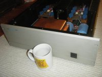
As far as grounding, I find it quite odd that the amp, having a HUGE copper bus bar wrapping around and bolted to the chassis, with the power caps and transformer taps attached, has the ground of the power cord attached to chassis in a different location with a shitty little screw.
(you can't see the bus bar across the bottom well, but you get the idea)
Attachments

Last edited:
Parts cost to lash one up should be under a fiver (GBP). The safety issue is that is should be away from being touched and unable to touch anything around it. It just goes in series with one side of the mains. Don't know how effective it is as I have never tried it.
Does the noise from the tranny vary at different times of day as the mains may be "purer" and closer to sinusoidal.
The ground of the power lead I assume is a safety ground. It looks fine for the purpose.
Does the noise from the tranny vary at different times of day as the mains may be "purer" and closer to sinusoidal.
The ground of the power lead I assume is a safety ground. It looks fine for the purpose.
Yup. Parts is cheap (although I can assure you I spent quite a bit overall on this relay project).
DC filters can be very effective. The PS does exactly what it says it does and works well on my other components, not so much on this amp.
I do not notice a variance during the day, but there are probably measurable differences
So, on the ground, does the whole amp makes it return to ground back through the transformer? Looks like it would have to, since (-) mains side of the tranny attaches directly to the (-) side of the power cord and gets plugged directly into the wall. I can't see how else that would work otherwise. I dunno.
Not quite sure I understand the last question 🙂
The signal parts of the amp don't have to be mains grounded at all. They may or may not be... or may be tied via a resistor even. No current should flow into the mains ground, it's purely a safety feature. If the case of the amp became live due to a fault, then the current flows into ground and the resulting overload blows the fuse.
When signal grounds are connected to the mains ground is when "ground loop" problems occur, which can cause hum etc.
- Status
- Not open for further replies.
- Home
- Amplifiers
- Power Supplies
- Swappin' Mech Power Relay for Solid State