I appreciate your input, does this diagram below shed any other light for you on the subject?Once again, switched and/or fused AC power neutrals are dangerous and probably not legal.
Well I think that this diagram is the best so far.
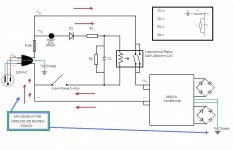
This is the complete representation of the circuit, up to the point of rectification to the rest of the amplifier.
The proposed added Circuit comprises only of C1,D1,R1 and R2(bleeder).
Removal of those 4 components leaves everything just as it is in its original form with 120v AC going directly to the relay coil and 120v AC going to the transformer.
As you can see, the relay circuit would indeed be fed directly from 120v AC. And what I'm trying to do is feed a lowered DC voltage to the relay coil to quiet it down.
My only other concerns are that this layout is 100% correct, that the ground/neutral is fine as is, and any potential safety concerns.
Next round of questions would be component types and values
Thank you Mooly and everyone very much for all the input.
Attachments
Last edited:
Would this be an instance where a ceramic disc cap would be acceptable, since its just being used to drive the coil?
Would this be an instance where a ceramic disc cap would be acceptable, since its just being used to drive the coil?
Only an electroylitic will be available in the required range of values and voltage ratings... around 47 to 100uf (microfarads) at 250 volt DC working voltage (for 120vac mains).
Thanks that saved me some trouble.
This is also very interesting, I was looking at the set up on the Nelson Pass BA-1 and the usage of thermistors along with the 2 x .0033 caps for filtering. You know, this looks like a good way to go.
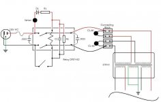
Check out the differences between the original layout as it exists now, and the combination of your suggestion + BA-1 idea below.
Honestly, other then the in-rush protection and filtering, I can't tell which is really better here. (although the Pass layout's symmetry looks cool😎)
Having the 2 poles paralleled (++) or having 1 pole on (+) and 1 pole on (-). What's the big difference?
With the original parallel, the transformer goes directly to ground once the connection is complete. To me that doesn't seem like a bad thing.(edit: the transformer to ground is the shortest possible length in the original layout(2))
This is also very interesting, I was looking at the set up on the Nelson Pass BA-1 and the usage of thermistors along with the 2 x .0033 caps for filtering. You know, this looks like a good way to go.
Check out the differences between the original layout as it exists now, and the combination of your suggestion + BA-1 idea below.
Honestly, other then the in-rush protection and filtering, I can't tell which is really better here. (although the Pass layout's symmetry looks cool😎)
Having the 2 poles paralleled (++) or having 1 pole on (+) and 1 pole on (-). What's the big difference?
With the original parallel, the transformer goes directly to ground once the connection is complete. To me that doesn't seem like a bad thing.(edit: the transformer to ground is the shortest possible length in the original layout(2))
Attachments
Last edited:
Having two poles paralleled increases the current handling in theory. In practice it's open to debate the contacts will never operate absolutely together. Overall the reliability is probably better though. The thermistors simply prevent the huge inrush currents that you get with large transformers... again it's for reliability and allows a more sensible fuse value to be used.
The diagrams... I still thing the way I drew it in post #35 is the starting point.
The second diagram above has the coil back on AC as original. The first diagram won't "kick" the relay hard... so you need lower value resistor and large value cap... which is less convenient and runs hotter.
The diagrams... I still thing the way I drew it in post #35 is the starting point.
The second diagram above has the coil back on AC as original. The first diagram won't "kick" the relay hard... so you need lower value resistor and large value cap... which is less convenient and runs hotter.
Ok, but I think that those #35 drawings, using a single diode, is going to be half wave, so it'll be more like 85vdc wouldn't it. I'd need to use a bridge rectifier @170v.
But even then... I bet that the coil wont handle a ton of DC.
The highest DC handling Coil made by Magnecraft, in the W199 series, is 24vdc on a coil of the same resistance (290ohm). There are 110vdc and 48vdc versions, but the resistance is waaaay higher (6000-1200ohms).
It's days like this I wish I had some good variable power supplies...
Ok, but I think that those #35 drawings, using a single diode, is going to be half wave, so it'll be more like 85vdc wouldn't it. I'd need to use a bridge rectifier @170v.
Yes and no. Yes it's half wave.
85Vdc... no. The cap charges to the peak value of the AC rms value which is 120*1.414 = 170 vdc. There is no load across the cap remember when the amp is OFF. When ON, the relay gets that full 170vdc as charge supplied by the cap. The voltages across the caps only fall under load (when relay is on)
The relay doesn't have to handle "a ton of volts"... that's the whole point. It operates in this circuit at far lower voltage (the holding voltage). It only sees 170vdc for a fraction of a second... long enough for the relay to pull in smartly.
Yes and no. Yes it's half wave.
85Vdc... no. The cap charges to the peak value of the AC rms value which is 120*1.414 = 170 vdc. There is no load across the cap remember when the amp is OFF. When ON, the relay gets that full 170vdc as charge supplied by the cap. The voltages across the caps only fall under load (when relay is on)
Ah, ok I get that now. Full wave is just more efficient / less ripply which is not important for this application.
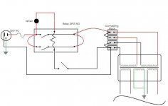
#35 drawing makes sense except we did talk about placing the switch so it doesn't stay connected in the "off" position. I know I've done alot of drawings but I keep rethinking since the schematic vs real physical layouts have varied since I started.
Please, If you could look again at these two, one is adding the same circuit in #35 (however, switch omits cap connection in "off") but look at the all the connection points. If this is wrong then I may have to perform some physical re-wiring inside this amp moving forward.
Thanks Mooly!
Attachments

No good... the second diagram doesn't allow the cap to charge when the amp is off. And that's whats needed to pull the relay in.
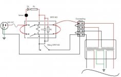
Look at this rearranged diagram.
And it's one of those things where you just have to experiment a bit with it all.
Resistor R1 needs to be as high as you can get away with, but with a margin of "safety". So if the relay just "holds" with say 40 volts, then think of decreasing the resistor to give around 60 volts across the coil. Make sure the wattage is OK.
Resistor R2... use a high value, say 470 k
I have added C2. Try the circuit without and with. I would suggest around 47uf for starters, same as C1
Attachments

Ok I see now. So should I shoot for X-type caps - polarized? (I see you mentioned at least 240v, not that this is going to the UK, but using 600v couldn't hurt)
Also, Can I simply divide the wattage needed for each resistor, if I use series connections with multiple resistors? Like if I start with 1.5kohms 15w, would 500/5w x 3 be ok?
I'm going to start at 24vdc and work a little upward.
Last, but not least, any concerns about "flyback-current" from this coil? R2 might catch it anyway.
(p.s: I had a dream about a "normally closed" relay where voltage is only applied to the coil to turn the amp off.....)🙄
Use good quality electroylitic caps. They an only ever "see" the peak mains voltage so 250 volt working is fine for 120vac mains.
Any caps that go across the 120 volt line must be rated for twice that peak voltage... that's probably where you have got the Class X and Y from. So that's 400v caps
NEVER CONNECT an electroylitic across AC.
You are correct with the resistors 🙂
"Flyback" or back EMF. A good point actually. It's probably kinder to the switch to include it, and reduce the possibility of any "RF" interference as the contact opens.
There are no issues with it causing problems damage wise, and the original diagram doesn't have it anyway. To include it you put a reverse biased diode across the coil.
Which brings another point... make sure the diodes are rated OK voltage wise. You want a P.I.V. (Peak inverse voltage) of at least 400 volts for 120 vac.
1N4007's are a good choice (1000v)
That's easy to do 😉
Any caps that go across the 120 volt line must be rated for twice that peak voltage... that's probably where you have got the Class X and Y from. So that's 400v caps
NEVER CONNECT an electroylitic across AC.
You are correct with the resistors 🙂
"Flyback" or back EMF. A good point actually. It's probably kinder to the switch to include it, and reduce the possibility of any "RF" interference as the contact opens.
There are no issues with it causing problems damage wise, and the original diagram doesn't have it anyway. To include it you put a reverse biased diode across the coil.
Which brings another point... make sure the diodes are rated OK voltage wise. You want a P.I.V. (Peak inverse voltage) of at least 400 volts for 120 vac.
1N4007's are a good choice (1000v)
(p.s: I had a dream about a "normally closed" relay where voltage is only applied to the coil to turn the amp off.....)🙄
That's easy to do 😉
I picked up some 1N4005's and some extra ceramic resistors. The resistors I have are 1.3k, 100, 50, 10. However, I wasn't able to source the caps at that voltage locally so I'll have to order some. I did find a 150uf 400v in an old printer supply, but it turned out that the damn thing was glued in! I actually tried that supply, which had 30vdc out, worked like a charm, snapping the contacts down tight.
Seems like I'll need the cap(s) to even begin to measure things. I tried just connecting the diode with 1500ohms resistance on a bread board with 120v AC, with just the multimeter connected, no load.
-Wildly random. Maybe I need to connect a load to get a reading...
Now looking at the dropper calculator (diode resistor)with no cap, I could be too high so yeah I see now how the play works.
Oh and I did see an identical NC relay, a drop in replacement to what I have, but it does create some other complications: thermal sensor will no long function to turn off, and the amp will be engaged when I plug it in (could switch initially with power strip though)
You have to build it as I showed... the caps are needed... without and it really is just half wave pulses feeding the relay.
You have to build it as I showed... the caps are needed... without and it really is just half wave pulses feeding the relay.
Indeed. Parts should be in by Friday. I'm looking forward to it too, so like, I can listen to music and stuff🙂
So what do you think about the NC-relay? you mentioned it was easy to do. Just curious.
So what do you think about the NC-relay? you mentioned it was easy to do. Just curious.
That's something you can make as simple or complex as you want. NC and the amp is on.
You need a supply to switch it off, one that remains present when the amp is off too.
Options... the easy one, a small transformer, or use a "wattless dropper" arrangement.
There's always ways and means... it's just how complex you want it all to be.
a NC relay will mean your amp will get power (for the duration of the relay switching time (20ms) when you plug it in to an active mains outlet or when mains power is restored after a blackout (power outage) usually when power quality is not good.
You could use a latching relay with 2 poles, 1st pole for Transformer Active and the second pole to select between Set & Reset on the relay. Then your mains switch becomes a Momentary action.
*Not tested* just thinking up a way to have you amp on and NO relay coil current.
You could use a latching relay with 2 poles, 1st pole for Transformer Active and the second pole to select between Set & Reset on the relay. Then your mains switch becomes a Momentary action.
*Not tested* just thinking up a way to have you amp on and NO relay coil current.
yeah, could use a NC, run a power cord to the coil off a strip with delay turn-on for the amp section/always on for the coil. Have the strip default off when AC goes out or browns.
A Latch would need some different switch.
I've actually been surprised about the lack of information everywhere concerning relays. I expected to also see something regarding them on Pass's threads and on his site. He points specifically to varivac or whatever. I don't think the wife would appreciate that in the living room-lol.
I even tried a sealed Tyco mech relay with nearly the same specifications. Still obnoxious in its coil vibration. SSR's produce ripply AC, so those I will not bother with.
I would have liked a drop in relay replacement for simplicity, but I'm going for the dropper circuit as it seems the best of the options. Less intrusive to the whole amp.
Initial Test
Initial test with a single diode and a 680ohm resistor in series(+),
47uf cap paralleled after (+/-) yields about 170vdc with no load.
For a test load, I used 300ohms of resistance (close to the coils res=290), and measured approximately 20vdc across the load.
Now this seems sensible, but I can't help feeling I'm forgetting some important calculation😕
It looks like I'm "sending" 20v to the load? Or am I sending allot more and the load makes it look lower? I'm a little confused sorry.
- Status
- Not open for further replies.
- Home
- Amplifiers
- Power Supplies
- Swappin' Mech Power Relay for Solid State