Edit Nov 2, 2021: Gerbers for the LuFo amp PCB needed for this project can be found here. A huge thank you for JPS64 for his generous time in making these layouts for the DIY community!
This is a spin-off of the LuFo amplifier discussed here, but it is sufficiently different enough that I did not want to confuse the technical detais already discussed in the other thread. Basically take two LuFo's, and connect them to a common inductively coupled choke with two primary windings, each going to ground, and wound such that the phases of the windings are opposite when referenced to a common ground. Then remove the AC coupling capacitors and connect the load directly between the two amps. Drive the amps with a powerful balanced preamp. You now have a balanced output symmetric amplifier. The name, although suggestive of similarities with Mr Pass’ Super Symmetry topology, is clearly not a SuSy per the Pass patent, since there is no intrinsic feedback between the two halves through a resistor as pointed out by Indra and ZM. However, there is inductive coupling/feedback between the two halves via the common core of the transformer load (note the LTSpice directive “K L1a L1b 1”). And as confirmed by Zen Mod below, the inductive coupling via the shared transformer core qualifies this as a SuSy type amp.
This has only been done in LTSpice, but it seems to make sense and the advantages are: DC coupled output, lower distortion, and higher maximum power (100W) for the same PSU rail voltage, in this case, 28v single rail. The dual primaries inductor will probably require a custom job, or a creative person can remove the secondaries from a microwave oven transformer (MOT) and rewind a second primary in the space where the secondary was once occupied. The performance is quite good with an 8w into 8ohm predicted performance of 0.007%THD.
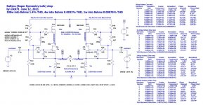
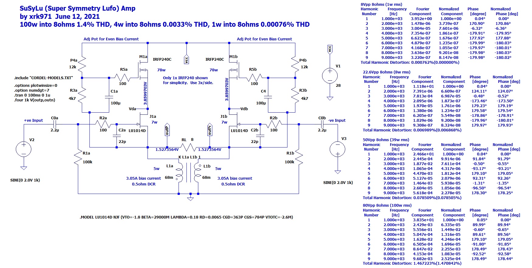
Here is the simplified schematic - you wil notice each half is identical to the schematic for the LuFo amp with exception of no output coupling cap. It would be a good idea to use the nicely matched power JFET Lu1014D's that Woofertester provided using the generous donation of LU1014D's that Mr Pass provided. One needs to adjust the bias currents on each side until the voltages at the output nodes match in order to reduce the DC current that would flow through the speakers since no coupling cap is present. One could install the coupling cap on one side and that would eliminate the DC offset concern. However, that would negate one of the primary advantages. The cascode MOSFETs is shown here as a single unit when in reality, 3x are used to spread the heat load across the heatsink. Schematic edited to show inductive coupling via the transformer loading:

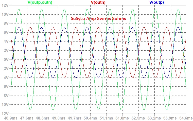
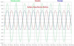
Here is the simulated time-dependent signal output on the positive leg, negative leg, and the difference across the speaker load for the 8w case:
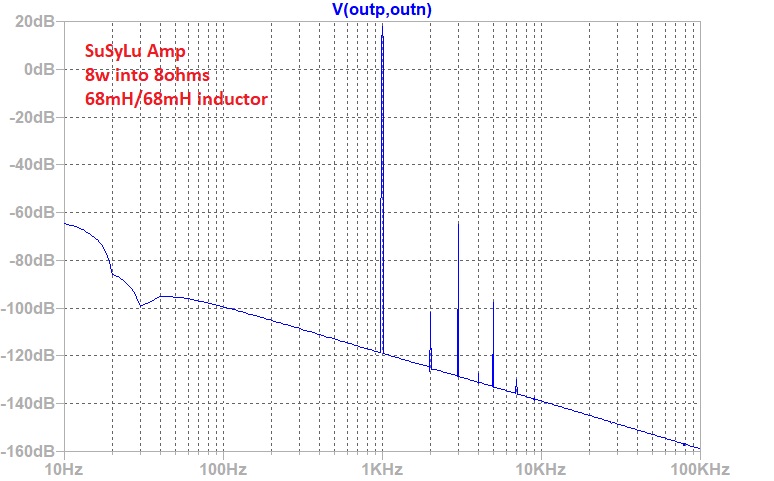
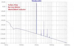
Here is the FFT for the 8w case with the inductors wound symmetrically at 68mH per side. We can see that they symmetric arrangement reduced second order distortion and so the third order dominates. This has a very solid state feel to the sound:
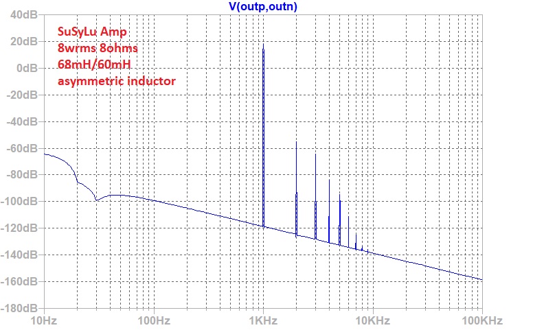
If we purposely made one of the windings different, say 60mH instead of 68. This will introduce slight asymmetries that will help reduce the third harmonic and other odd distortion figures.
Edit Sept 22, 2021: SuSyLu has been tested and verified to make 100w (31.7Vrms or 89.7vpp) into a 10ohm dummy load with only 27.6Vdc single rail PSU from a 400VA 24v toroidal trafo.

Sound clips here: SuSyLu Where Are You?
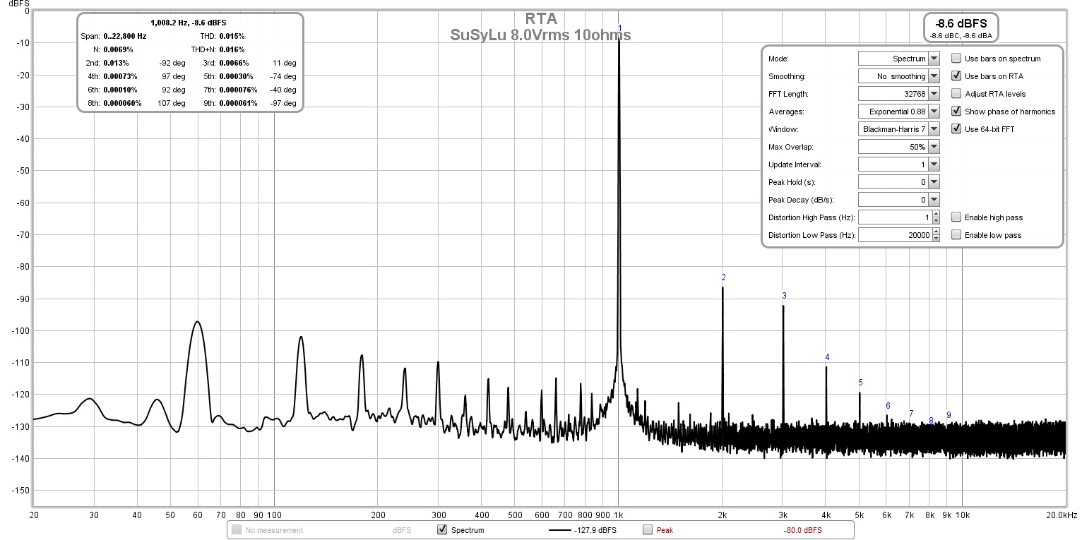
Here is FFT for 8.0Vrms into 10ohms, he THD is 0.015%:
This is a spin-off of the LuFo amplifier discussed here, but it is sufficiently different enough that I did not want to confuse the technical detais already discussed in the other thread. Basically take two LuFo's, and connect them to a common inductively coupled choke with two primary windings, each going to ground, and wound such that the phases of the windings are opposite when referenced to a common ground. Then remove the AC coupling capacitors and connect the load directly between the two amps. Drive the amps with a powerful balanced preamp. You now have a balanced output symmetric amplifier. The name, although suggestive of similarities with Mr Pass’ Super Symmetry topology, is clearly not a SuSy per the Pass patent, since there is no intrinsic feedback between the two halves through a resistor as pointed out by Indra and ZM. However, there is inductive coupling/feedback between the two halves via the common core of the transformer load (note the LTSpice directive “K L1a L1b 1”). And as confirmed by Zen Mod below, the inductive coupling via the shared transformer core qualifies this as a SuSy type amp.
This has only been done in LTSpice, but it seems to make sense and the advantages are: DC coupled output, lower distortion, and higher maximum power (100W) for the same PSU rail voltage, in this case, 28v single rail. The dual primaries inductor will probably require a custom job, or a creative person can remove the secondaries from a microwave oven transformer (MOT) and rewind a second primary in the space where the secondary was once occupied. The performance is quite good with an 8w into 8ohm predicted performance of 0.007%THD.
Here is the simplified schematic - you wil notice each half is identical to the schematic for the LuFo amp with exception of no output coupling cap. It would be a good idea to use the nicely matched power JFET Lu1014D's that Woofertester provided using the generous donation of LU1014D's that Mr Pass provided. One needs to adjust the bias currents on each side until the voltages at the output nodes match in order to reduce the DC current that would flow through the speakers since no coupling cap is present. One could install the coupling cap on one side and that would eliminate the DC offset concern. However, that would negate one of the primary advantages. The cascode MOSFETs is shown here as a single unit when in reality, 3x are used to spread the heat load across the heatsink. Schematic edited to show inductive coupling via the transformer loading:
Here is the simulated time-dependent signal output on the positive leg, negative leg, and the difference across the speaker load for the 8w case:
Here is the FFT for the 8w case with the inductors wound symmetrically at 68mH per side. We can see that they symmetric arrangement reduced second order distortion and so the third order dominates. This has a very solid state feel to the sound:
If we purposely made one of the windings different, say 60mH instead of 68. This will introduce slight asymmetries that will help reduce the third harmonic and other odd distortion figures.
Edit Sept 22, 2021: SuSyLu has been tested and verified to make 100w (31.7Vrms or 89.7vpp) into a 10ohm dummy load with only 27.6Vdc single rail PSU from a 400VA 24v toroidal trafo.
Sound clips here: SuSyLu Where Are You?
Here is FFT for 8.0Vrms into 10ohms, he THD is 0.015%:
Attachments

Last edited:
X, SuSy (Super Symmetry) as used by Nelson Pass is a patented topology described in his U.S. Patent #5376899 - art_susy.pdf, not a follower.
Last edited:
I admit, not the same topology, as I have no gain, no folded cascode, but it is simple cascoded power JFET with a choke load instead of CCS and it is a symmetric amp in response to Woofertester’s challenge for a SuSy with the LU1014D here. But did you see the available output power for a 28v rail amp? Up to 100w for a SE Class A amp capable of swinging 80vpp.
Here is the schematic from the patent:
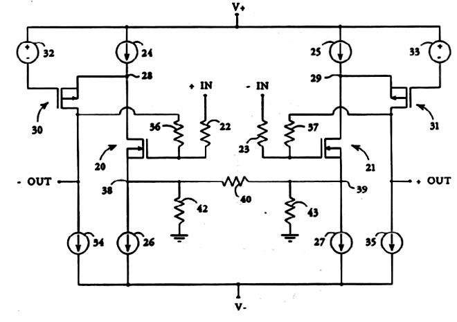
Here is the schematic from the patent:
Attachments

Last edited:
I got nothing to add. 🙂... The rules are simple. You design a SUSY LU1014D amplifier and post a working LT SPICE model of the amp you designed including all files to run the sim. If you do not know what SUSY is, if you are not versed in LT SPICE, you have to go figure it out...
...No arguing or complaining. Just submit your design and be patient...
There is no need for you to show me schematic of SuSy topology. What really concerns me is the potential confusion to newbees due to the misleading association of your follower circuit to long established SuSy topology on first post of this thread. Perhaps you can elaborate a bit more to rectify the issue.Here is the schematic from the patent:
there is no X feedback in circuit, so no SUSY
buffer or no buffer, that's no issue - intrinsic coupling betwen two phases is what counts
my Iron Pumpkin (Bal) is SUSY - even of preceded with separate buffers, balanced output autoformer is having SUSY intrinsic, same as every xformer with balanced input is having
buffer or no buffer, that's no issue - intrinsic coupling betwen two phases is what counts
my Iron Pumpkin (Bal) is SUSY - even of preceded with separate buffers, balanced output autoformer is having SUSY intrinsic, same as every xformer with balanced input is having
There is no need for you to show me schematic of SuSy topology. What really concerns me is the potential confusion to newbees due to the misleading association of your follower circuit to long established SuSy topology on first post of this thread. Perhaps you can elaborate a bit more to rectify the issue.
there is no X feedback in circuit, so no SUSY
buffer or no buffer, that's no issue - intrinsic coupling betwen two phases is what counts
Indra and ZM,
Thanks, and post 1 updated to clarify.
What do you think of the intrinsic inductive coupling happening between the two halves at the inductive load? These are not independent inductors but a transformer. This is done through the coupling directive “K L1a L1b 1”.
Last edited:
Something like this but wound with two primaries and connected so that each half is in anti-phase. Strong magnetic or inductive coupling in the reactive load will be present.
https://www.diyaudio.com/forums/attachments/pass-labs/959257d1623536005-lufo-amp-39w-se-class-28v-rail-img_20210612_235730-jpg
https://www.diyaudio.com/forums/attachments/pass-labs/959257d1623536005-lufo-amp-39w-se-class-28v-rail-img_20210612_235730-jpg
that detail skipped ( xformer, not two independent coils) - was before first morning coffee kicked in
if proper xformer, yes - there are enough elements for SUSY - xormer is giving it
if proper xformer, yes - there are enough elements for SUSY - xormer is giving it
Thanks for confirming ZM. Maybe the name is not so far off then...
Perhaps this diagram would have been more clear given the coupled output transformer:
Perhaps this diagram would have been more clear given the coupled output transformer:
Attachments

Last edited:
... or a creative person can remove the secondaries from a microwave oven transformer (MOT) and rewind a second primary in the space where the secondary was once occupied.
Another option is to take a primary from another equal MOT and mount it in secondary position ???
Last edited by a moderator:
Yes, there is a video that shows a guy cutting the weld off of a MOT in order to install a new primary. You have to re-weld it though. I think it might be easier to wind a new primary into the space taken by the original secondary.
I’m going to either order some C core blanks or I will remove the secondary from a MOT and rewind the added primary. I ordered the 80ft spool of 14ga magnet wire already.
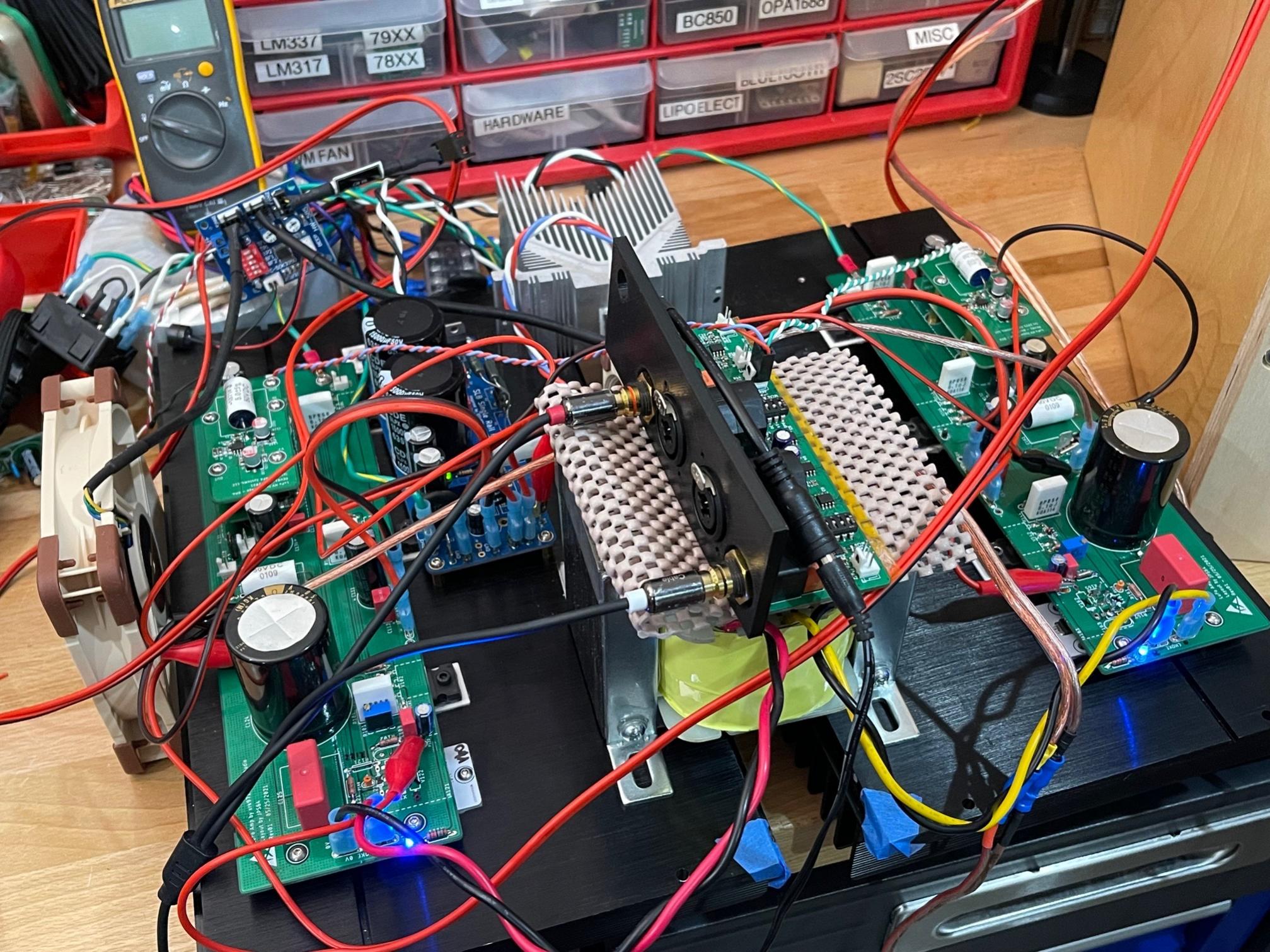
The monoblock chassis that I ordered have 5Ux350mm heatsinks in each side, so in theory, I can just install a LuFo amp board on each side and they can share a common PSU and power trafo. I just need the dual primary transformer and should be able to test this out.
The monoblock chassis that I ordered have 5Ux350mm heatsinks in each side, so in theory, I can just install a LuFo amp board on each side and they can share a common PSU and power trafo. I just need the dual primary transformer and should be able to test this out.
Last edited:
This amplifier works with identical topology:
Grandinote - Shinai - en
Output semiconductors are high power BJT's as emitter followers, coupled to a centertapped toroidal choke.
15V power supply; 3A DC current; pure class A.
One of the best amplifiers I heard (I had it on loan for evaluation).
Don't worry too much about the THD FFT; unequal inductances also means different DCR's and possible DC offset when using no output caps.
A clone of this amp is on my to-do-list; however with tube front end.
The same 600 watt HiB c-core will be a perfect fit.
Hi Daanve,
That Grandinote Shinai looks interesting. I never knew something like this was commercially made with BJTs. Their description has no topology schematic that I could find but they said push-pull transistors. P-P is not what I would use to describe this topology. Is it an air gapped toroidal transformer?
That Grandinote Shinai looks interesting. I never knew something like this was commercially made with BJTs. Their description has no topology schematic that I could find but they said push-pull transistors. P-P is not what I would use to describe this topology. Is it an air gapped toroidal transformer?
I checked it when I had it on loan 😀.
It is pure class A push pull.
Toroidals are not easy to check for airgap as the windings hide the core, but in theory the DC currents cancel so no need for airgap.
However... in practice a small airgap is needed to accept some unbalance which will mostly be there.
Here, a c-core comes in handy as the airgap is so easy to apply.
but in theory the DC currents cancel so no need for airgap
Why don't we just use a toroidal power transformer then as a test? I realize ferrite cores suck for audio frequencies but I have about 30 in my 'donut shop'. 😀
You can certainly try.
Take care of DCR of the two halves when you want to use it to self-bias a BTL LuFo.
Balance of secondary halves of power supply toroidals might be sub-optimal but for an experiment..
Take care of DCR of the two halves when you want to use it to self-bias a BTL LuFo.
Balance of secondary halves of power supply toroidals might be sub-optimal but for an experiment..
The DCR of the primaries on my power toroidal donuts typically are 5ohms. So too high to work.
Although distortion is showing up near the peaks, it is always fascinating to see 80Vpp into 8ohm load from an amp with a 28Vdc single rail:
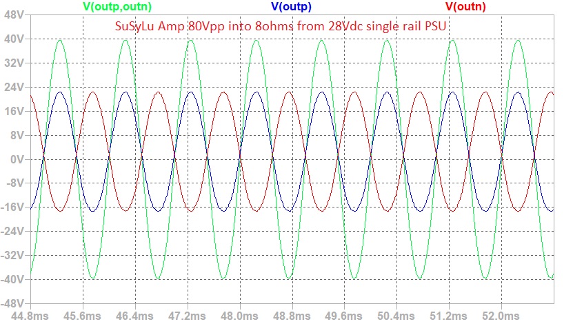
Although distortion is showing up near the peaks, it is always fascinating to see 80Vpp into 8ohm load from an amp with a 28Vdc single rail:
Last edited:
- Home
- Amplifiers
- Pass Labs
- SuSyLu Where Are You?