
Haha, for sure. 🙂
Even $0.49 Keystone test lead clip points are sometimes overkill. Nice touch though - it depends on how often you think you need to plug it in to adjust.
Even $0.49 Keystone test lead clip points are sometimes overkill. Nice touch though - it depends on how often you think you need to plug it in to adjust.
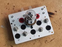
Very true. I don't think I'll connect DVMs very often, but I just had a bunch of those banana jacks in the drawers, and I liked the idea of using them. The jacks also serve as mounting points for the parts on the rear of the mounting plate. Sort of an over-the-top way of making a point-to-point wiring.
If someone wants to design a more down-to-earth PCB for the SuSu T. PuckFo: Be my guest!
If someone wants to design a more down-to-earth PCB for the SuSu T. PuckFo: Be my guest!
would you show the full buffer schematicOkay, maybe I need to explain why I did what I did. My ideas may be off, so please let me know if I am missing something (and what).
Zener connection at the gate:
I put the Zenter directly at the gate (not before the the gate resistors) because I was thinking to use the gate resistor as a "fuse". It the gate voltage goes too much negative, the Zener will start to conduct, and the current will flow through the Zener. If the voltage applied to the gate resistor becomes very negative (aproaching the -70 V), the current will increase and blow up the gate resistor, thereby disconnecting and protecting the gate.
Also, Nelson seems to connect the Zener directly to the gate, not before the gate resistor (example: https://www.firstwatt.com/pdf/art_diy_sony_vfet_pt2.pdf).
+/-70 V for the buffer:
As mentioned in the thread/post mentioned earlier, the buffer FET (STF3LN80K5) has very low input capacitance (1 pF or so) if it has 45 V or more across drain/source. To maintain the low input capacitance even under full AC swing (25 Vpk or so), we need 45 V + 25 V = 70 V.
- Home
- Amplifiers
- Pass Labs
- SuSy T. PuckFo