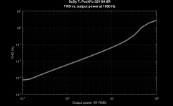
I spent some quality time in the workshop. Here are some distortion measurments from the output stage. The OPS was driven by a low-distortion test amplifier AC coupled to the THF51 gates. DC biasing was done via 100k resistors (not via the FET buffers shown in the schematic of post #31).
If the idle currents of the two OPS halves are nicely balanced, the 3rd harmonic dominates, and the 2nd is hardly visible at 1 W output. If desired, the biasing of the two halves can be set to a slight imbalance, which brings up the 2nd harmonic. I am not in one of the "2nd > 3rd" or "2nd < 3rd" camps, so I am happy with both.
The THD is at single-digit ppm levels at low power, and increases smoothly with power. The usual "kink to the sky" when the amp starts clipping does not happen here, as the amp has very smooth clipping.
Attachments

I realised that I confused the 6H5pi/6N5P double triode with the 6E5P tetrodes that I found in my stash. I don't have any 6H5pi/6N5P double triodes, but I have many 6SN7, which are speced very similar to the 6H5pi/6N5P. I therefore changed the design to use the 6SN7 instead. I hope I'll find some time to mess with the tube front end during the next few days!
Attachments

It would be nice if the get a 6SN7 where the two triodes are "balanced"?
They are probably not from spec?
They are probably not from spec?
I am not quite sure what you mean. There is a pot on the grid bias of each triode, so the biasing and balance of the front end can be adjusted. Or did you mean something else?
With "balanced tube" I meant that the two triodes in the 6SN7 are "identical". So they have same gain etc. Same as two matched transistors. I think you call this kind of double triode tubes "balanced" if they two triodes have same curves. You then need to be able to curve trace the tubes or buy one where this has been done. Probably from a known source that can be trusted. It all depends if you need or want it. I think only very few tubes are "balanced" from spec. A tube like Telefunken ECC 803S was balanced out of the box (from what I have heard but have no experience with those. Most sold on internet are fakes).
And you need a 6SN7 for each channel?
A matched pair would then be two that are balanced and then two identical of those.
You probably need quite a lot tubes to start with to find such a matched pair. To do this you need to get "untested" tubes......etc......that is complicated 🙂
Better forget about this and just build it using random tubes 🙂
Ok, I see what you mean. I did a very similar long-tailed pair in my KT66 Mc Gyver Amp, where I included a "balancing pot" to tweak the symmetry between the two triodes. Once I tested the amp, it turned out that the "balancing pot" was not necessary. All my 6SN7 tubes had sufficiently "matched" triode units, and the amp always gave pretty good THD with the pot in the middle position.
Oh, and I totally like the idea of curve tracing and matching parts, even if it's not necessary. Matching parts (even if it's unnecessary) is a nice way to deal with my OCD 🙂
Edit: matching the SITs in the output stage may actually turn out to be more important when it comes to optimizing the linearity of the amp. I was lucky to have 28 x THF51, which gave me a nicely matched quad...
you're forgetting that LTP in this case - is having a really long tail ........... 
and, if that isn't enough of Great Equalizer, there is always some spare gain left, to equalize it more
and, if that isn't enough of Great Equalizer, there is always some spare gain left, to equalize it more
I am building a "machine" (which goes very slowly) which can perform burn-in of those double triode type tubes and also check if a tube is "balanced" by looking at the intensity of 3 leds. It is a kit and I am not the designer. I am not a tube expert at all. But I like to learn......
28 THF51.......that is not bad. I can see prizes years back was a lot less than now.
Interesting if you get all the voltage levels to "fit". You will get a nice voltage swing from the anode of the tube I assume.
Interesting if you get all the voltage levels to "fit". You will get a nice voltage swing from the anode of the tube I assume.
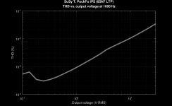
I made a test setup of the 6SN7 input stage today. Once I fixed some wrong values of the resistors for grid biasing, everything biased up as expected. AC voltage gain is 15.6, and the stage works pretty clean. The THD data in the attachment were done with a random 6SN7 that came out of the drawer, and without tweaking the biasing points.
Attachments
Last edited:
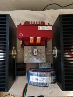
The "solder pad" you have between the screw-isolator and THF-51 housing......do you get enough contact presure.....also for the "long run".......for a good electrical connection?
I was thinking about putting a washer + split-washer in between to keep a nice contact-presure over time?
Is there a "best-practise" for such a connection?
I was thinking about putting a washer + split-washer in between to keep a nice contact-presure over time?
Is there a "best-practise" for such a connection?
Pass DIY Addict
Joined 2000
Paid Member
Looks great, Mat! I’d be inclined to copy your final version, but I don’t have a sufficient quantity of matched pucks. Instead, I’ll be enjoying your progress vicariously 😁
Interesting question, and I have no good answer except that I think that maaaany transistors were mounted and connected in this way until now. As far as I can tell, things worked out well in the past. If someone knows more about this, I'd love to hear about it 🙂The "solder pad" you have between the screw-isolator and THF-51 housing......do you get enough contact presure.....also for the "long run".......for a good electrical connection?
I was thinking about putting a washer + split-washer in between to keep a nice contact-presure over time?
Is there a "best-practise" for such a connection?
How many SITs do you have? Which ones? If you have some THF51 with curves, we could try to match them with mine. Or you send them over for curve tracing and matching.Looks great, Mat! I’d be inclined to copy your final version, but I don’t have a sufficient quantity of matched pucks. Instead, I’ll be enjoying your progress vicariously 😁
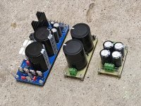
That board on the photo is just a piece of paper with a printout of what it should be sometime in the future 🙂I'm curious about the board that the 6SN7 is plugged into.
The idea is to use an aluminium plate that holds the tube and most of the parts of the amplifier circuit. The plate will also hold the bias adjustment pots (10 turn precision potentiometers) and some banana jacks that connect to the various bias points underneath the plate (for easy DVM connections). I will not use a PCB, as I am not very good with making those, and the circuit is simple enough for point-to-point wiring.
The schematic of the HV power supply is in post #31. Part values are not yet final. I will need to figure out how to fit the PSU (mainly the capacitors) into the limited space available inside the chassis.And the HV power supply.
Kk, thanks for the update. If you find the sweet spot for the 6SN7, it should sound really sweet. They do like high plate voltage.
I think the main schematic has PSU2 and PSU3 connections reversed.
I think the main schematic has PSU2 and PSU3 connections reversed.
Yes, you are right. I am still adding some other minor changes and details. I will post the revised schematics when they are ready.I think the main schematic has PSU2 and PSU3 connections reversed.
- Home
- Amplifiers
- Pass Labs
- SuSy T. PuckFo