Another one 🙂
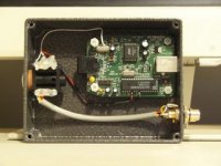
Is the long wires from the power caps a problem?
If so is there a better way to connect them to the board?
Regards H@kan
Is the long wires from the power caps a problem?
If so is there a better way to connect them to the board?
Regards H@kan
An externally hosted image should be here but it was not working when we last tested it.
An externally hosted image should be here but it was not working when we last tested it.
Nice Work!
Hi there Hakan,
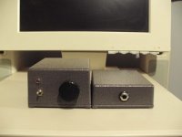
Nice job, looks real strong!
Where did you get a housing like that? it almoast looks like casted brass!
special!
Greetings,
Arjen
Hi there Hakan,
Nice job, looks real strong!
Where did you get a housing like that? it almoast looks like casted brass!
special!
Greetings,
Arjen
Another armored design, very impressive.
How did you get the top edge to fit so snug? Mitered edge?
Did you buy the plates pre-cut or can you do that yourself?
As for the leads from the tank caps: common wisdom is to keep them short to avoid forming an oscillator from capacitance and inductance. You could at least twist them, I think.
How did you get the top edge to fit so snug? Mitered edge?
Did you buy the plates pre-cut or can you do that yourself?
As for the leads from the tank caps: common wisdom is to keep them short to avoid forming an oscillator from capacitance and inductance. You could at least twist them, I think.
Arjen Wrote:
I would like to have some feedback on what you guy's would like to see.
In my humble opinion the existing design is pretty good Arjen, however some small changes I would sugest:
As you say, thicker copper and/or some of the rails a bit wider .
Perhaps a bit more room on board for the input caps & enough room for at least 2x 2200uF "tank Cap's"in place of the existing 220uF's.
DC offset trimming on board.
Better quality / tolerance SMD's.
Certainly happy with my Mk1 version though & listening to it now fed by a DAC / Headphone amp I have just completed. Sounds Sweet..
ElFishi said:Another armored design, very impressive.
How did you get the top edge to fit so snug? Mitered edge?
Did you buy the plates pre-cut or can you do that yourself?
As for the leads from the tank caps: common wisdom is to keep them short to avoid forming an oscillator from capacitance and inductance. You could at least twist them, I think.
Thanks! I will twist the wires. The plates is not miltered they just "come together" when belt sanding them. Cutting the plates is done by a regular buzz saw. Alu is not that hard so many regular wood tools will do.
Thanks paul,
I think if i need to get these things made, i better do it good, if not best for the money i spend on it,
i dont want to make things overly complicated, no need and it dosnt help for design quality either is my idea,
but im open for suggestions, and have started a new thread
i invite all people that use the TA2024 to give me some comments so that we can end up with a better product.
ZL2BPS said:Arjen Wrote:
I would like to have some feedback on what you guy's would like to see.
In my humble opinion the existing design is pretty good Arjen, however some small changes I would sugest:
As you say, thicker copper and/or some of the rails a bit wider .
Perhaps a bit more room on board for the input caps & enough room for at least 2x 2200uF "tank Cap's"in place of the existing 220uF's.
DC offset trimming on board.
Better quality / tolerance SMD's.
Certainly happy with my Mk1 version though & listening to it now fed by a DAC / Headphone amp I have just completed. Sounds Sweet..
Hi Paul,
Could you please,show me the inside of Headphone amp that u had completed it. I would like to make one like you
 Please Please^^
Thank U..i'm waiting to see them
Varisign Wrote:
Could you please,show me the inside of Headphone amp that u had completed it.
No credit to me, & no time to take photos at present. Refer Perco's post No 569 some weeks back. I was given one of these boards some time ago, not working.
After reading Perco's post, I simply repaired it & put it into a small case which matches my amp. I slightly re-aranged things (output caps), & fitted a 6.5mm headphone socket & switched RCA's for output.
It makes an incredible diference when using my laptop as source.
Will take some photos when time permit's.
Paul
What ohm values is preferable for volume control potentiometer?
Is there any better way to be able to controle the volume than using a pot on the line in?
Is there any better way to be able to controle the volume than using a pot on the line in?
Potmeters
Hi there volny,
Ive used 50K pots before, all fine, it works well. i have those alps pots here,Original, sell them for 10 euro.
mostly doh i use it with my computer, then a pot is not needed.
Hope that helps.
Arjen
Hi there volny,
Ive used 50K pots before, all fine, it works well. i have those alps pots here,Original, sell them for 10 euro.
mostly doh i use it with my computer, then a pot is not needed.
Hope that helps.
Arjen
The other option is to place a buffer inbetween. I have Pedja rogic discrete buffers that I intend to use with mine.
I'll report when I get a chance to check out the sound. I'm still doing the other modifications to the amps. I am documenting any mods on the web.
I'll update with the differences made by the buffers in the nest week or two.
I'll report when I get a chance to check out the sound. I'm still doing the other modifications to the amps. I am documenting any mods on the web.
I'll update with the differences made by the buffers in the nest week or two.
I got a hit on my site which came from a refferal on a malaysian site
The thread in particular that i was linked to from was this one
Look familiar?
Not sure if this has been pointed out yet, but those buying from Arjen might be interested in the 70 pages of discussion!
The thread in particular that i was linked to from was this one
Look familiar?
Not sure if this has been pointed out yet, but those buying from Arjen might be interested in the 70 pages of discussion!
justblair said:I got a hit on my site which came from a refferal on a malaysian site
The thread in particular that i was linked to from was this one
Look familiar?
Not sure if this has been pointed out yet, but those buying from Arjen might be interested in the 70 pages of discussion!
Thank you for that link!
ta 2024
hi blair
great website,i think you are right about the capacitors on these boards,300uf a side should be enough.IMHO they are assymetricallly wired so to speak,see pic.
ps nb this mod effectiveley removes supply protection diode

hi blair
great website,i think you are right about the capacitors on these boards,300uf a side should be enough.IMHO they are assymetricallly wired so to speak,see pic.
ps nb this mod effectiveley removes supply protection diode
Thanks... I'm working on it...
Interested in the mod you show. Is there an advantage do you think in splitting the power lines that way? I'm used to the idea of star earthing, this would be the same principle... Star powering?
Interested in the mod you show. Is there an advantage do you think in splitting the power lines that way? I'm used to the idea of star earthing, this would be the same principle... Star powering?
Re: ta 2024
hi albin,
pretty interesting mod there..
any significant gains in the sonic department?
thanks. have a nice day.
ps.
this is my very first posting in diyaudio. 😀
great discussion guys!
hi albin,
pretty interesting mod there..
any significant gains in the sonic department?
thanks. have a nice day.
ps.
this is my very first posting in diyaudio. 😀
great discussion guys!
albin said:hi blair
great website,i think you are right about the capacitors on these boards,300uf a side should be enough.IMHO they are assymetricallly wired so to speak,see pic.
ps nb this mod effectiveley removes supply protection diode
Welcome to Jazzy... Haven't we met before somewhere?
For those who have ordered boards from Arjen, Jazzy and his friends over in Malaysia have already been working hard on these boards.
Definately worth some cross forum collaboration here...
JB
For those who have ordered boards from Arjen, Jazzy and his friends over in Malaysia have already been working hard on these boards.
Definately worth some cross forum collaboration here...
JB
- Status
- Not open for further replies.
- Home
- Amplifiers
- Class D
- Sure Electronics Tripath boards?