billnchristy said:Question:
I am going to have to assume that the 3 power caps on each side are parallel right?
If that is the case couldn't you just add one across the "plug" instead of soldering onto the existing ones?
Please kick me if I am wrong...just explain why while you are beating me mercilessly. 😉
All 6 100uf/16v caps on board are in the same 12V rail, you can put one or two and three, no problem.
How does the sleep pin work? If I short it to ground will it go to sleep?
This is basically what I'm using for a power switch, as I'm using the 2.5mm power connector on the PCB.
This is basically what I'm using for a power switch, as I'm using the 2.5mm power connector on the PCB.
Maybe not - Will this work:
I have +vdd going thru a 1MR resistor to the sleep terminal thru a switch.
Will this work or will something nasty happen when I turn the switch on?
I have +vdd going thru a 1MR resistor to the sleep terminal thru a switch.
Will this work or will something nasty happen when I turn the switch on?
Does that cut the volage down to 5v? I believe that is what mute and sleep need to set it into a logical high.
Problem solved, I just went for an external power switch in the end. I gave up with the whole sleep thing... Pics coming. 🙂
EDIT: Piccies:
I have yet to put a volume control in, I thought I had the right pot but it turned out to be mono 🙁
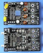
Underneath:
Also, what does the remove c3,24,c13,c21 and replace with caps mod do, as I have not done this yet.
EDIT: Piccies:
I have yet to put a volume control in, I thought I had the right pot but it turned out to be mono 🙁
An externally hosted image should be here but it was not working when we last tested it.
Underneath:
An externally hosted image should be here but it was not working when we last tested it.
Also, what does the remove c3,24,c13,c21 and replace with caps mod do, as I have not done this yet.
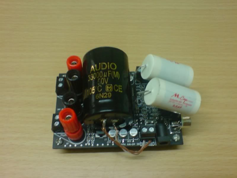
Your certainly not going to be short of capacitance! Mines only had a few hours use so far, and isn't sounding too bad with some 8ohm speakers....
So the c3,24,c13,c21 remove (and replace) mod inproves the sound. I was wondering what good values are? It is part of the zobel thing, where a different value will give you a different filter frequency?
I'm guessing anywhere between 1uF - 5uF would be an OK replacement?
So the c3,24,c13,c21 remove (and replace) mod inproves the sound. I was wondering what good values are? It is part of the zobel thing, where a different value will give you a different filter frequency?
I'm guessing anywhere between 1uF - 5uF would be an OK replacement?
I am using 6.0 uF and the bass feel really strong with no noise pop-up problem at turn on. It's there but it is the same as I use 2.2 uF.I'm guessing anywhere between 1uF - 5uF would be an OK replacement?
dannyt said:
I am using 6.0 uF and the bass feel really strong with no noise pop-up problem at turn on. It's there but it is the same as I use 2.2 uF.
I should have some 1uF caps somewhere, I'll add them today with any luck. 🙂
FOUND: Inexpensive Case for the Tripath Board
I found this at Bed Bath and Beyond. I think its the perfect size (6"x9"x2.5"), allows some elbow room all around. The walls are .35" thick. It is made of bamboo. It does not come with a top. $6.99. They usually have a 20% or 30% coupon out if you really want to go low budget. Hopefully, it will drill well, bamboo can be tough.
I found this at Bed Bath and Beyond. I think its the perfect size (6"x9"x2.5"), allows some elbow room all around. The walls are .35" thick. It is made of bamboo. It does not come with a top. $6.99. They usually have a 20% or 30% coupon out if you really want to go low budget. Hopefully, it will drill well, bamboo can be tough.
Attachments

That bamboo looks nice. Maybe a piece of perspex would make a good top? I just used the packaging for some car bulbs I bought recently... The board fits ok, and as it's plastic all the connections are isolated.
I've just removed c3 and c24. What a difference! Before the sound would change when adjusting the volume before, but now it stays the same. It's now crisp and clear, before it sounded like my speaker was in another room. The sound isn't too different to my 41Hz.com Amp6basic really. I'm tempted to pick up another board just in case this one dies as they cost so little...
I've just removed c3 and c24. What a difference! Before the sound would change when adjusting the volume before, but now it stays the same. It's now crisp and clear, before it sounded like my speaker was in another room. The sound isn't too different to my 41Hz.com Amp6basic really. I'm tempted to pick up another board just in case this one dies as they cost so little...
Well guys, I finally decided to have a go last night and dug one of the boards out......
Needless to say, I got carried away as usual and started drilling the board to get the input resistors close to the pins. This works perfectly for me as I use the Bias pin for grounding the inputs and it all ties in nicely. No solder on there yet, just wanted to see how it panned-out.
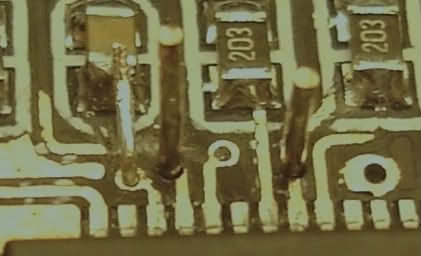
I could leave OAOUT2 FB resistor in its normal position (just swap for a 36K), but OAOUT1 is going to be soldered close to the pins. (too far away at the moment).
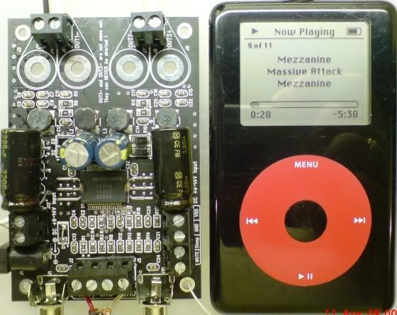
NO input caps required due to the DC coupling method, this will be a power amp for a modified iPod (using the Wolfson DSP).
So that correction circuit will be severed on INV1. (INV2 already done).
Then it's just the power caps and maybe tinker with the output stage. Barry, what did you find on the output circuit? Anything worth changing?
TTFN
Lee
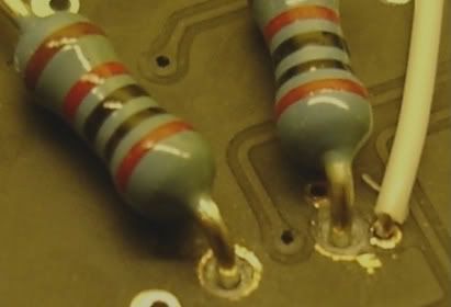
Needless to say, I got carried away as usual and started drilling the board to get the input resistors close to the pins. This works perfectly for me as I use the Bias pin for grounding the inputs and it all ties in nicely. No solder on there yet, just wanted to see how it panned-out.
I could leave OAOUT2 FB resistor in its normal position (just swap for a 36K), but OAOUT1 is going to be soldered close to the pins. (too far away at the moment).
NO input caps required due to the DC coupling method, this will be a power amp for a modified iPod (using the Wolfson DSP).
So that correction circuit will be severed on INV1. (INV2 already done).
Then it's just the power caps and maybe tinker with the output stage. Barry, what did you find on the output circuit? Anything worth changing?
TTFN
Lee
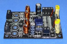
....and finally got around to finishing the job last night.
36K FB resistors - AOOUT1 on underside of board.
1000uf and 2200uf per side on power rails.
Ground tied to BIAS cap.
No DC Servo - 90 & 50 mv offset... I can live with that for the clarity of having absolutely NO CAPS!😀
The similar size of the DIY-Pod and amp will make the case compact and tidy... especially when it has a built-in dock conector😉
Too late to plug it into my main speakers but my test bench monitors are telling me this was a worth while project 😀
I wonder if there is a way of getting the DC servo to work in this configuration?
http://www.maurarte.com/T-AMP.htm
This site was mentioned before in other threads, but the sure is at the top now.
This site was mentioned before in other threads, but the sure is at the top now.
Attachments
Hi, could some-one please post a diagram of the headphone amp modification mentioned earlier in this threat - I remember audio1st saying he'd built one?
- Status
- Not open for further replies.
- Home
- Amplifiers
- Class D
- Sure Electronics Tripath boards?