It just depends on what you are satisfied with I guess... sorry about the pun!🙄
Why the German language by the way? I don't understand that ****...
Gettin' off topic, but in the U.S. and G.B., "Schadenfreude" is a commonly used term to describe the feeling a person experiences when getting undue pleasure at another's expense. I prefer enjoying music and not being neurotic about implementing constant changes (relatively speaking!). We differ, alright? Tot ziens!
______________________________________________
Back on topic . . . To me the most annoying thing about the Sure boards is something that Barbieboy has experienced: the difficulty in desoldering/soldering these boards, since they aren't typical through-plated double-sided boards, which I assume is common these days for boards populated with SMDs. I've wondered if there might be an alternative. I would happily pay up to $100 for a heavy through-plated board with the SMD devices we prefer already soldered on, with the other cap and resistor positions unfilled. I imagine Sure Electronics isn't geared for requests like this, but there may be other options in China.
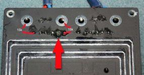
Barbieboy,,check the resistances against the ones in the picture. If the side nearest the arrow reads zero ohms then it could be that you need to clean the area around the pad pointed to, it could be grounding, or you may need to replace that cap completely and solder in a different position.
Attachments
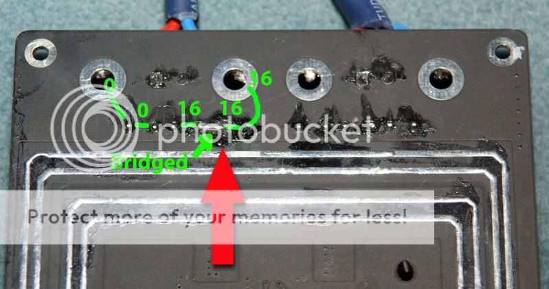
Hi Barbieboy, try adding a link as shown in 1st pic..
To check your inductors are soldered to the pads, you should have near zero resistance between the points in pic 2..
Hi and thanks Audio1st, did the link as you directed and checked the readings in pic2. Still getting the same clicking out the tweet and screeching out of the woofer.... There was zero resistance on both channels. Must be one of the caps blown ?
Please measure all caps. I think you might have burned one
Looks like I am getting no reading from C47
Measure resistance through each cap. The bigger ones should read 16K because of the circuit they are in. Although the one with the missing pad may not be in the circuit. The smaller one should read 32K.
.
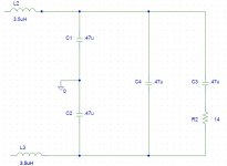
The reason that the one pad won't take solder is probably because the pad is no longer there. You will have to run a jumper according to the schematic to the next closest pad. That is probably the shorted cap that any way. If it is shorted, you will need to replace them all so that they match. Always check the DC offset again with a resistor for a load before connecting to your speakers and fine tuning.
Thanks Scott, but is starting to look like C47 cap is the problem, ironically one that I did not remove and is the least burnt by the side of the soldering iron or them all....
Barbieboy,,check the resistances against the ones in the picture. If the side nearest the arrow reads zero ohms then it could be that you need to clean the area around the pad pointed to, it could be grounding, or you may need to replace that cap completely and solder in a different position.
Ok thanks, and thanks for the red lines to show me where to dig. Ok, the end cap C47 is giving me no reading. For the others please see my pic. The other channel reads as Scott said = small cap 32, big caps 16 and 16 out to the speaker connectors
It looks like you will need to replace c47, (680nF). Zero ohms means it is shorted to ground. Remove and remeasure the board in case the board has a short and not the cap.
replace the caps
You need to replace the caps. I would do them all. I use .47uf for all and a Zobel of .47uf with 15ohm/5watt. I like the Dayton foil caps which you can't easily get. The Epcos are quite popular right now. Many people theorize that the flying leads from using a larger size cap will increase radiation of the 650KHz switching wave but my amps measure very low EMI even with the ultra low value Wurths. Others theorize that the sonics of the caps in this application are irrelevant because the filter knee is so far out of the audio band and they are installed as a shunt, not as coupling. I haven't tested this yet but will compare the stock output caps to the Daytons soon to find out. As long as you are forced to replace anyway, I would use better caps which will be bigger, on the under side of the board, and don't worry about the exposed leads. They are not any problem. You might as well change the input caps now as long as you are ordering. 2.2uf?Any ideas what I should do next guys ?
Attachments
Radial caps
Some of the higher spec radial lead caps from Panasonic or Vishay might also be very nice to replace with and would tend to fit in the stock location.
Any ideas what I should do next guys ?
Some of the higher spec radial lead caps from Panasonic or Vishay might also be very nice to replace with and would tend to fit in the stock location.
It looks like you will need to replace c47, (680nF). Zero ohms means it is shorted to ground. Remove and remeasure the board in case the board has a short and not the cap.
Ok, just removed C47, and get zero readings from the board and the same from the removed cap itself.
On C49 getting a reading of 16. But for the same cap on the other channel that works fine I am getting a reading of 32.... I believe that should be the correct reading according to Scott.
You need to replace the caps. I would do them all. I use .47uf for all and a Zobel of .47uf with 15ohm/5watt. I like the Dayton foil caps which you can't easily get. The Epcos are quite popular right now. Many people theorize that the flying leads from using a larger size cap will increase radiation of the 650KHz switching wave but my amps measure very low EMI even with the ultra low value Wurths. Others theorize that the sonics of the caps in this application are irrelevant because the filter knee is so far out of the audio band and they are installed as a shunt, not as coupling. I haven't tested this yet but will compare the stock output caps to the Daytons soon to find out. As long as you are forced to replace anyway, I would use better caps which will be bigger, on the under side of the board, and don't worry about the exposed leads. They are not any problem. You might as well change the input caps now as long as you are ordering. 2.2uf?
Hmm, are these Input caps ? If so, I have already replaced these with clarityCaps. Its the Outs that are giving me all the grief !
Some of the higher spec radial lead caps from Panasonic or Vishay might also be very nice to replace with and would tend to fit in the stock location.
Thanks Scott, so presumably as you said, I should replace them also on the channel that works to keep things even.
Shopping list ?:
680 / JM100 x4
224 / J100 x2
Thanks Scott, so presumably as you said, I should replace them also on the channel that works to keep things even.
Shopping list ?:
680 / JM100 x4
224 / J100 x2
Get some desolder braid and some isopropyl alcohol to clean up the flux after, it will make the job easier... try sanding your soldering iron tip with 400grit and re-tin it with solder before you start.... good preparation is about 80% of a good soldering job...
I've just tracked mine throught the UPS website... should have them tomorrow, cant wait 🙂 I've ordered 2 x 2*100 modules and a 14A 24v meanwell. I hope they drive my mission M35 speakers, Im going to Bi-Amp them..
MISSION M35i SPEAKERS (PAIR) - available from Superfi UK Visit http://www.superfi.co.uk/index.cfm/page/moreinfo.cfm/product_id/2085 for details
Is anyone else driving large speakers with theirs?
Large speakers
Yes, I'm driving some NHT's and then a sub, a, a center two sides and two rear.
Yes, I'm driving some NHT's and then a sub, a, a center two sides and two rear.
Get some desolder braid and some isopropyl alcohol to clean up the flux after, it will make the job easier... try sanding your soldering iron tip with 400grit and re-tin it with solder before you start.... good preparation is about 80% of a good soldering job...
I've just tracked mine throught the UPS website... should have them tomorrow, cant wait 🙂 I've ordered 2 x 2*100 modules and a 14A 24v meanwell. I hope they drive my mission M35 speakers, Im going to Bi-Amp them..
MISSION M35i SPEAKERS (PAIR) - available from Superfi UK Visit http://www.superfi.co.uk/index.cfm/page/moreinfo.cfm/product_id/2085 for details
Is anyone else driving large speakers with theirs?
Ok thanks, I did spray the board with a cleaning solution, hope that helped.
I have two 100w TA2050 and biamping also. But got some sort of earth loop noise when running them both off the one Meanwell 24v. bought a second one and no more troubles. But whatever you do don't crack up the voltage to 27v (there is a pot on the rear), sounds horrid and abrasive.
Make sure your power supply is set to either 230V or 115V.
Are you refering to the ground loop noise when running 2 modules from the 1 smps?
Yes, I am running two 4X100's from one Meanwell SMPS.
You will get an annoying hum if the SMPS is not set correctly.
You will get an annoying hum if the SMPS is not set correctly.
Yes, I am running two 4X100's from one Meanwell SMPS.
You will get an annoying hum if the SMPS is not set correctly.
Thanks, I was worried that I might have to fork out more money there for a second....
- Status
- Not open for further replies.
- Home
- Amplifiers
- Class D
- Sure Electronics New Tripath Board tc2000+tp2050