I've bought two Sure ADau1701 DSP boards to play with, building active speakers.
In a class D thread I just read:
So... what's wrong with the Sure Adau1701 DSP boards that makes them "suck"?
In a class D thread I just read:
Don´t use Sure DSP. It suck´s.
This one, at close range, is much cheaper. It has all the stuff Sure forgot and you can only add at huge cost´s.
ADAU1701-2In4Out | 3e Audio
Two of them should be enough.
So... what's wrong with the Sure Adau1701 DSP boards that makes them "suck"?
Build quality is low. I had one doa as well. The output is low on them but I think they are quite cool little objects. I used one in a BT speaker and it worked great. No complaints there but I haven't used one for any critical situations.
Have one as well + output board and programmer. Works quite well.
Only complaint is the pop at power on and off, as it does not have any mute function, but I think this goes for a lot of solutions, including the MiniDSP.
Starting to work on my own ADAU1701 board 😉
Only complaint is the pop at power on and off, as it does not have any mute function, but I think this goes for a lot of solutions, including the MiniDSP.
Starting to work on my own ADAU1701 board 😉
The price difference is so little, you can not even buy the missing connectors and the bare output buffer IC´s for it. Things the Sure does not have.
With the 3e all you need and will miss with the Sure is already there.
Get both and you will see how unrefined the Sure is. Just the bare minimum to make the ADAU1701 work. What you do not see or read is not there. You have to connect anything to these tiny pins which will not lead to a nice installation.
The result in the digital domain will be the same, but the analog part, if you care for sound quality, is much better.
PS If you buy the Sure extension board, you only get 3 output´s (how stupid!) of 4 and nothing else of value. Which makes the Sure more expensive than the 3e DSP.
Just have a close look and you will see I´m right.
Just have a close look and you will see I´m right.
Build quality is low. I had one doa as well. The output is low on them but I think they are quite cool little objects. I used one in a BT speaker and it worked great. No complaints there but I haven't used one for any critical situations.
DOA is not a problem with Parts Express, they'll send a new one instantly. Especially since I've ordered the relabeled Dayton versions - Dayton might just have better (their own?) QC on their relabeled versions? (One can dream 🙂)
Low output - I'll have to see how that affects me, it'll be hooked up to 2 3x200W amps but I'll find out what the SNR is 😛
Oh well, for the price it's all just a big adventure.
The nice thing about building amplifiers with building blocks like these is that if one building block doesn't perform satisfactory, you can just pull it out and replace it with something else 🙂
Last edited:
The price difference is so little, you can not even buy the missing connectors and the bare output buffer IC´s for it. Things the Sure does not have.
With the 3e all you need and will miss with the Sure is already there.
Get both and you will see how unrefined the Sure is. Just the bare minimum to make the ADAU1701 work. What you do not see or read is not there. You have to connect anything to these tiny pins which will not lead to a nice installation.
The result in the digital domain will be the same, but the analog part, if you care for sound quality, is much better.
They're indeed so cheap I might just order a 3E one as well just to play with / compare.
In what ways is the 3E's analog part better?
PS If you buy the Sure extension board, you only get 3 output´s (how stupid!) of 4 and nothing else of value. Which makes the Sure more expensive than the 3e DSP.
Just have a close look and you will see I´m right.
Since I'll be using them to power 3-way tri-amped speakers that's not a problem for me.... currently.
I don't expect to be moving to 4-way, but hey - you know how that goes, so I might want to along the way 🙂
Last edited:
I take your point on PE being able to replace but having boards DOA isn't so easy to accept if you think that it made t out of the factory defective then how long until it becomes defective in the real world with use?
I think the output is low because it has no output preamp and another member has suggested it doesn't even have output filters. I haven't full investigated this. Also, given that you are using high power amps using balanced connections would be a better move. With a Sure board you can only have two outputs balanced (inverting one channel of a pair).
With the 3E (which Turbo suggested to me) you get an op amp per output which is reassuring.
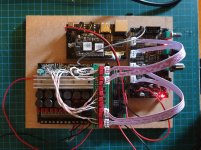
Attached is my 3E DSP board project so far.
I think the output is low because it has no output preamp and another member has suggested it doesn't even have output filters. I haven't full investigated this. Also, given that you are using high power amps using balanced connections would be a better move. With a Sure board you can only have two outputs balanced (inverting one channel of a pair).
With the 3E (which Turbo suggested to me) you get an op amp per output which is reassuring.
Attached is my 3E DSP board project so far.
Attachments

With the Sure you have the bare DSP outputs.
The 3e board has high quality buffer IC´s at all 4 outputs, balanced. So you have no problem to drive the (usual following) power amp in differential mode. Which should give lower ground noise.
You could retrofit these to the sure at extra cost and complication.
Further, the implementation of the pots with the sure is problematic, as you can not use them the way the 3e-Audio work. You have to remove them first.
These are all problems you only run into when you use the board.
DOA has been reported with too many Sure boards. They seem to go out untested.
Attached is my 3E DSP board project so far.
Looking good! What's the third board?
Looking good! What's the third board?
Cheers man!
You mean the Arylic Up2Stream Pro?
Another reason to bash the sure board is labelling. Although they are cute and small this means the labelling is not obvious and everything is bunched together. I have killed two of them through putting connectors where they shouldn't go. Admittedly this is my fault but with the 3e there is clear labelling and with different connectors spaced apart.
Cheers man!
You mean the Arylic Up2Stream Pro?
Yes, that's it. I remember a thread about using it with a DSP. IIRC the only drawback is that you have to use the analog out vs the IIS since the IIS is fixed at 44.1 KHz and incompatible with DSP's 48 KHz. I think the author actually changed the DSP's clock crystal to force the DSP to 44.1 KHz.
PS - I see they have V2 versions of both the Pro and mini versions of the board.
Well that knackers one of my weekend plans to connect Arylic to the DSP via I2s!
Yeah, it's definitely a letdown. Here's the link to thread I mentioned. The author changed the ADAU1701 crystal so it would operate at 44.1 KHz instead of 48 KHz. I'm not sure why he chose such a large crystal as he could have stayed with the same size as the original.
The V2 version of the Pro does have a line out connector in addition to the 3.5 mm connector. But I think they're the same output signal, just different connectors.
Well that knackers one of my weekend plans to connect Arylic to the DSP via I2s!
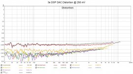
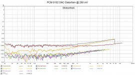
You could work around the problem by using THIS PCM5102 DAC. It would add additional D/A (DAC) and A/D steps (3e DSP), but would probably still sound better than the Arylic analog out. I’ve successfully used that DAC to provide two additional output channels to the 3e DSP. And the DAC’s distortion levels match the 3e DACs.
At first I ran into the problem of where to find 5 VDC to power the DAC. After poking around a bit I found a source of 5 VDC on the DSP unit. It's an un-populated capacitor footprint just above the 5V LED on the DSP. The DAC only requires 40 mA. I contacted 3e Audio about using the 5 VDC from the DSP and they said no problem.
Attachments

I had looked at that "Wiimu A31" thread a while back and dismissed it, because the A28 modules that I have used are I2S masters, not slaves. You don't have to send them a clock, because they provide it for you, and you can program the ADAU1701 PLL to use that clock. Any of the WiFi modules that have optical/Toslink out will be I2S masters to drive the SPDIF transmitter.
Unfortunately, the ADAU1701 learning module doesn't have a pin dedicated to an external clock input, so you would need to do some surgery on the board to bring in the clock.
I have 10 of the "Rev 3" boards in this article that support the Wiimu A28 module, and 1 of them is partially built. I haven't tested this board because I got too excited by the Rev 4a version and never finished assembling the Rev 3 boards. If you want some of these boards, I can send them, but first I need to finish the assembly and test to verify they work OK. However, I've gotten to a point in my life where I don't enjoy SMD soldering unless I'm tipsy, so you would have to send some good quality bourbon before I could send you boards. And none of that cheap stuff--my threshold is Knob Creek. 😀
I had looked at that "Wiimu A31" thread a while back and dismissed it, because the A28 modules that I have used are I2S masters, not slaves. You don't have to send them a clock, because they provide it for you, and you can program the ADAU1701 PLL to use that clock. Any of the WiFi modules that have optical/Toslink out will be I2S masters to drive the SPDIF transmitter.
Unfortunately, the ADAU1701 learning module doesn't have a pin dedicated to an external clock input, so you would need to do some surgery on the board to bring in the clock.
I have 10 of the "Rev 3" boards in this article that support the Wiimu A28 module, and 1 of them is partially built. I haven't tested this board because I got too excited by the Rev 4a version and never finished assembling the Rev 3 boards. If you want some of these boards, I can send them, but first I need to finish the assembly and test to verify they work OK. However, I've gotten to a point in my life where I don't enjoy SMD soldering unless I'm tipsy, so you would have to send some good quality bourbon before I could send you boards. And none of that cheap stuff--my threshold is Knob Creek. 😀
Is knob creek expensive and available on amazon? 😉
You could work around the problem by using THIS PCM5102 DAC. It would add additional D/A (DAC) and A/D steps (3e DSP), but would probably still sound better than the Arylic analog out. I’ve successfully used that DAC to provide two additional output channels to the 3e DSP. And the DAC’s distortion levels match the 3e DACs.
At first I ran into the problem of where to find 5 VDC to power the DAC. After poking around a bit I found a source of 5 VDC on the DSP unit. It's an un-populated capacitor footprint just above the 5V LED on the DSP. The DAC only requires 40 mA. I contacted 3e Audio about using the 5 VDC from the DSP and they said no problem.
Cheers man, I'll work with the line out for now but I'm going to order that board as well!
Graham –
Here’s how to hook up the DAC to the 3e Audio DSP, step-by-step.:
First you need to configure the 1701 so the multipurpose GPIO pins are outputting I2S data. The 1701 supports up to 4 L-R pairs (8 individual channels) of I2S data in addition to the four DACs. The pins we’re interested in configuring are:
MP6 = Sdata_out0; MP7 = Sdata_out1; MP8 = Sdata_out2; MP9 = Sdata_out3
MP10 = In_LRCLK_Out; MP11 = In_BCLK_Out
We only need one of the data pairs so let’s pick MP6 as our data source. Go to the “Hardware Configuration” tab in SigmaStudio, select the “ADAU1701” block so it’s outlined in green, right click and select register window. Look for the “GPIO” section. Click on the MP6 drop down check mark and select “Output Sdata_out0”. In the same way select “In Lrclk_out” for MP10 and “In Bclk_out” for MP11. Some or all of these might already be set up. Then look for the “Serial Output 1” section and select the “Master Mode” option. All the other default I2S settings worked for this DAC.
Note for those using the 3e Audio SigmaStudio source code:
You’ll notice that MP6 and MP7 are configured as “Input GPIO Debounce”, MP8 is configured as “Aux_ADC_3” (the treble pot) and MP9 is configured as “Aux_ADC_2” (the volume pot). So all four Sdata_out GPIO pins seem to be in use. The MP6 and MP7 pins may be used by the “Auto Source Selection” and “Auto Mute” blocks. It’s hard to tell since the source code for those blocks aren’t supplied. I sent an e-mail to 3e Audio about the subject today.
Next we need to add to the digital outputs to the SigmaStudio schematic. Go to that tab and drag the “output” control (found in the “IO” section) onto the schematic. From the control’s drop down list choose “DIG0. Repeat and select “DIG1”. These are the SDATA_0 Left and Right channels respectively. After that you connect those outputs just like a DAC output.
For the hardware connections: My previous post (#16) shows where to get the DAC 5 VDC. I attached a diagram showing where the other connections (BCLK, LRCLK and Data) are found on the DSP’s J5 connector. You can also get the ground from any of the even numbered J5 pins. I used pin-to-pin jumpers in my initial test.
You should be ready to go! Just remember the DAC’s max output is 2 Vrms which is less than the DSP DAC outputs.
Attachments

Last edited:
- Home
- Amplifiers
- Class D
- Sure Adau1701 DSP opinions?