Graham –
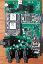
Here’s how to hook up the DAC to the 3e Audio DSP, step-by-step.:
Ern, you're an absolute gent! Thanks for that, It'll be really interesting to get it going.
It's kind of exciting. It means with a cheap AliExpress board and four DACs a cheap 2x4 balanced out DSP could be assembled quite cheaply!
From what I gather the two pots are still functional on the 3E board, that is correct? I'm going to copy this over to my thread so I have it for easy access! Thanks again!
I see the extension of the little DSP a bit critical.
If you use 8 outputs of the ADAU there should be a point where the DSP runs out of steam or memory. As far as I understand the number of filters you can use is limited. I know of commercial DSP´s, that develop very inconvenient effects when they are overloaded with instructions.
Maybe using a second ADAU may be the better idea, if you consider the work, parts and additional wires that mess up your installation. All to save, maybe, 15$.
If all you need are balanced out´s, use 4 little boards with the OPA1632 ?
Fully-Differential Audio Operational Amplifier OPA1632 Module ADC Driver Board | eBay
Last edited:
Yep, I completely take your point there. For me, at this stage I'm learning a lot so I am happy to experiment.
Thanks for the tip on the balanced boards. The benefit of the i2s outs would me you could use nicer DACs, I suppose and then use a board like you recommended. I dont think it would stress the board if one were you use my above suggestion tho as you arent processing any more signals just splitting and then inverting one after processing. Alas your suggestions makes that moot.
Thanks for the tip on the balanced boards. The benefit of the i2s outs would me you could use nicer DACs, I suppose and then use a board like you recommended. I dont think it would stress the board if one were you use my above suggestion tho as you arent processing any more signals just splitting and then inverting one after processing. Alas your suggestions makes that moot.
Last edited:
If you use 8 outputs of the ADAU there should be a point where the DSP runs out of steam or memory. As far as I understand the number of filters you can use is limited.
The ADAU1701 isn't powerful enough to implement long FIR filters, but it has plenty of "steam" for "conventional" IIR filters implemented with digital biquads. The ADAU1701 executes 1024 instructions every audio sample, and a 2-pole biquad requires 5 instructions. So you can implement over 200 biquads, or 25 biquads per channel if you have 8 channels. An 8-pole crossover requires 4 biquads for the LPF and another 4 biquads for the HPF, so 8 channels of 8-pole crossovers only uses about 1/3 of the ADAU1701 resources. That leaves plenty of "steam" left over for delays, volume controls, multiplexers and other DSP building blocks. Many of the DSP building blocks only require one or two instructions per block. And there is enough Data RAM for over 80 feet of total delay that can be allocated. For a lot of audio applications a single ADAU1701 provides plenty of horsepower and memory, even using all 8 channels.
I know of commercial DSP´s, that develop very inconvenient effects when they are overloaded with instructions.
The ADAU1701 always executes 1024 instructions per audio sample. It never gets "overloaded". If you have more than 1024 instructions, the compiler won't generate the code. If you have less than 1024 instructions, the chip runs "NOP" instructions to fill up the remaining time until the next audio sample arrives.
There are a lot of applications where a more powerful chip makes sense, but for many DIY active speaker applications the ADAU1701 is fine.
Last edited:
Is knob creek expensive and available on amazon? 😉
My wife bought me some. Now I need to see if the board works and modify some code. I'll get to use my new hand-held oscilloscope that just got delivered from China

Attachments
@Neil Davis
Thank you for explaining the limits of the ADAU1701.
So if a DSP can be feed with to many instructions (in most cases filters for equalizing the measured response of a speaker), it will probably not be ADAU1701 based.
I know of some PA DSP´s that run into problems very soon, if you use steep LP/HP filters, delays and then add just some equalizing points. So you have to take care what you correct and decide what is most important for your set up. All the years this seemed not really logical to me, because as you mention, the software should know the limits of the DSP chip.
Maybe just bad programming. I thought this would apply to other DSP´s too.
This makes the "little" 1701 even more interesting, as newer developments seem to aim for integrating the DSP into the D-amp. Sure cost saving for the industry, as passive x-overs are expensive and unable to correct cheapest loudspeaker chassis.
DIYS is somewhere in a no man´s land, as PA solutions are to expensive and take space, while the amp integrated DSP´s are not really flexibel enough for us.
So the ADAU1701 seems to be the device that is going to stay for a while?
Graham –
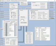
Note for those using the 3e Audio SigmaStudio source code:
You’ll notice that MP6 and MP7 are configured as “Input GPIO Debounce”, MP8 is configured as “Aux_ADC_3” (the treble pot) and MP9 is configured as “Aux_ADC_2” (the volume pot). So all four Sdata_out GPIO pins seem to be in use. The MP6 and MP7 pins may be used by the “Auto Source Selection” and “Auto Mute” blocks. It’s hard to tell since the source code for those blocks aren’t supplied. I sent an e-mail to 3e Audio about the subject today.
Next we need to add to the digital outputs to the SigmaStudio schematic. Go to that tab and drag the “output” control (found in the “IO” section) onto the schematic. From the control’s drop down list choose “DIG0. Repeat and select “DIG1”. These are the SDATA_0 Left and Right channels respectively. After that you connect those outputs just like a DAC output.
Hi Ern!
My DAC board arrived and seems to power up from the 5v pad, I solder a right angled pin on to it for dupont connector.
I followed your instructions to the letter, thanks for this again, but I have run in to a problem. I set output meters on all channels including the extra two digi outputs and signal is reaching them. When I plug the output of the DAC to an amp (I am using my wifes Bose to cut out any other anomalies) I get a very loud and distorted signal. It doesn't sound like regular distortion, though. Also, the volume control on the 3E board either turns this distorted output on or off with a short delay to either depending on the pot position. If the pot gets pass 10% the DAC output is on and distorted. If at 0 it goes entirely off after a second.
Is this to do with the 3E source code I am using?
Cheers man!
It could be the 3e source code. I deleted the code for all three volume pots when I tested the DAC and saved it as a new file. Try that and if it works try adding back each pot one at a time. In the long term I don't see using the volume pot anyway, maybe I'll keep the bass and treble.
More recently I had a problem where I wasn't getting output from any channels. So I deleted their "Auto Mute" block and the problem went away. But that was in the heat of the moment and I may have caused the problem.
I did get a response from 3e audio concerning if their "Auto Source Selection" and "Auto Mute" blocks use any GPIO pins:
My question: "I would like to keep the 3e Audio SigmaStudio “Auto Source Selection” and “Auto Mute” blocks in my DSP designs. Do either of those blocks turn on the LED or require the use of any GPIO pins? I don’t want to use a GPIO pin if one of those blocks need it."
Their response: "no GPIO in these block"
I have been very impressed with 3e's response to my questions. I have e-mailed them four times and have received a response in 1-2 days.
PS - It's also possible that the DAC's output (max 2 Vrms) is overwhelming the Bose input, depending on it's input sensitivity. Do you know the input specs for the Bose?
Last edited:
Thanks, Ern.
When you refer to deleting the code is it as simple as removing the modules?
I'll look in to the Bose aspect. Otherwise do you think using a DC isolator for that 5v might help?
Is sample rate an issue? All new territory for me, I appreciate you help!
When you refer to deleting the code is it as simple as removing the modules?
I'll look in to the Bose aspect. Otherwise do you think using a DC isolator for that 5v might help?
Is sample rate an issue? All new territory for me, I appreciate you help!
OK, I have tested output on a mixer with gain adjustment. Still distorted.
I created a new project file in Sigma Studio with just input and digi output and your settings with the same result.
Also, in either the 3E Sigma project file or mine a volume control in the schematic has no effect to the digi output
Perhaps a defective DAC board or maybe I've got some connections wrong? It is only 3 cables to attach plus VCC and ground to and from the 3E board. As I say, I'm new to this I2S lark so it's a bit confusing to debug.
Maybe I could try with my Sure board.
Perhaps I could post images of my physical connections to make sure I'm not a bone head. Sorry to be a drag!
Oh, I haven't written anything to the ROM of the 3E board, just run live from SS. 🙂
Last edited:
How about trying a "known good" (i.e. a DAC output) to the Bose. You'll need a spare 3-pin JST connector that you connect the DSP V+ and Gnd to the Bose input. That will be a good starting point.
Oops! I forgot to mention that all analogue outs are working fine to my TPA3116 or Bose so, I guess we can cross that off the list 🙂
Here are my connections:
Bclk (bck) to pin 15 - Green
Lrclk (lrck) to pin 13 - Purple
Sdata0 (data) to pin 11 - Blue
VCC and ground from empty capacitor pad and ground to the second row on J5. Hmmmmm.
Here are my connections:
Bclk (bck) to pin 15 - Green
Lrclk (lrck) to pin 13 - Purple
Sdata0 (data) to pin 11 - Blue
VCC and ground from empty capacitor pad and ground to the second row on J5. Hmmmmm.
Attachments


Call off the search!
Right, so I was looking through the datasheet and searched for FMT which is a three pin jumper selection on the DAC board. The board wasn't supplied with a jumper so I thought nothing of it before as I tried bridging various combinations of those pins whilst audio was playing to no avail. What I didn't do is bridge them then restart the whole system!
I guess the DAC needs to be rebooted with this selection made rather than during operation!
I feel bad, I should have noticed this sooner! 🙂
Man, I'm so hyped! Thanks Ed!
Like the say, the devil's in the details! My board came with the jumper installed so I never thought about it.
An update on this board...
I figured out how to use these A28/A31 Linkplay boards. They are usually slaves to an A/D converter, which provides the I2S clock. But then they are masters to the DAC and the SPDIF transmitter. So, you need to provide a 2.822MHz clock if you don't have the A/D converter. Once I provided a suitable clock, the chip outputted audio from Spotify and my cell phone via DLNA to my ADAU1701. I used this same clock for the ADAU1701 with PLL mode = 00, which the chip used to run at 45MHz.
So it looks like this board will work OK, once I add an oscillator to provide the sample clock. I've got a 3.072MHz oscillator on order, which should allow the ADAU1701 to run at a 48KHz sample rate.
Unfortunately, you can't use one of those low-cost ADAU1701 boards because you need to provide your own clock and you need to change the PLLmode to use a 3.072MHz reference rather than the 12.288 oscillator that is typically used. That means you need to solder all of those SMD parts for the custom ADAU1701 circuit. And for me that means I need Knob Creek or higher to make these boards. I'd prefer to buy a completed module for the ADAU1701 circuitry, but there doesn't seem to be anyway to get there with this design. Thank goodness liquor stores are still considered an "essential service" in Virginia during this COVID-19 crisis.
Attachments

Thanks for the update Neil. A question though: In this THREAD the OP just changed the ADAU1701 crystal from 12.288MHz crystal to 11.2896MHz, giving it a sample rate of 44.1 KHz. So in his case both the W31 and ADAU1701 had the same sample rate, but had separate clock sources. He claimed this worked fine so I assumed the I2S somehow managed to sync together.
So for those of us with ADAU1701 boards - couldn't we just change the clock on the Linkplay board to 3.072MHz and keep the current ADAU1701 clock?
So for those of us with ADAU1701 boards - couldn't we just change the clock on the Linkplay board to 3.072MHz and keep the current ADAU1701 clock?
Can anyone tell me the practical differences between the 3e adau1701 implementation and the Wondom / Sure board?
I ordered 2 Sure's to play with, are the 3e better audio quality wise?
I ordered 2 Sure's to play with, are the 3e better audio quality wise?
Thanks for the update Neil. A question though: In this THREAD the OP just changed the ADAU1701 crystal from 12.288MHz crystal to 11.2896MHz, giving it a sample rate of 44.1 KHz. So in his case both the W31 and ADAU1701 had the same sample rate, but had separate clock sources. He claimed this worked fine so I assumed the I2S somehow managed to sync together.
So for those of us with ADAU1701 boards - couldn't we just change the clock on the Linkplay board to 3.072MHz and keep the current ADAU1701 clock?
OK, I "sort of" see what he is doing now. He is doing what is recommended on page 18 of the ADAU1701 data sheet: using MP11 to provide a clock for the Linkplay module. MP11 is programmed to output 2.8224MHz by dividing the internal core clock by 16.
But I don't understand two things:
1) The UpStream module should already be providing a clock on this pin. On the A28 and A31 modules themselves there is no I2S clock--you must provide it. That additional circuitry on the Arylic board should have a clock--otherwise there would not be any I2S output. I assume there is some circuitry underneath the Linkplay module with an oscillator, but I can't see it. On the Dayton WFA28 boards, there is an ADC with an oscillator to provide the clock, along with a DAC. I'm guessing the DAC is the same one used on the Dayton boards: the ES7134--it looks like it is just to the left of the output jack on the Arylic board. But where is the oscillator that generates the I2S_CLK? And why don't you have to remove that clock when you connect I2S_CLK to MP11 of the ADAU1701 board?
2) Why does it matter whether the I2S_CLK from MP11 is 2.8224MHz or 3.072MHZ? And since this signal is generated from the ADAU1701 crystal, why should you have to change the crystal? These modules are suppose to be able to generate 24-bit audio up to 192KHz, so it should be as happy with an ADAU1701 using a 12.288MHz crystal as one with a 11.2896MHz crystal. But I'll be able to answer that question in a few days--just got in a shipment of oscillators.
Those are the same questions I had. It looks to me that in his setup both the Arylic board and the 1701 board would be trying to drive BCLK and LRCLK. I asked him a question in that thread just now, but he hasn't posted anything since January. So my hope for a response is low.
Okay so for the time being I'll continue this hobby project using the Dayton/Sure stuff, if it ever goes anywhere I'll probably start replacing parts with better ones. 🙂
Another question - the Dayton/Sure/Wondom DSP is powered using microusb.
Currently my case only contains the SMPS for the amp unit (36V).
Is it okay to connect a 36V->5V MicroUSB converter like this (Title is wrong, it takes 8v-52v as input, not 8v-25v) to the SMPS output (that's also powering the amp unit) or would that have negative effects on sound quality?
Last edited:
- Home
- Amplifiers
- Class D
- Sure Adau1701 DSP opinions?