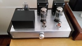
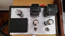
After various internal modifications to the amp: revision of the wiring (in particular ground), tube swap etc. I decided to move the toroid P.T. to the front of the chassis and thus insert the rectifier tube behi
I noticed an overall improvement on the left channel (even though is small) but then I also wanted to make a potentiometer change because it didn't convince me.
At that moment it happened that at the midpoint of the same there was a peak of "hum" on rotating the volume. After various checks I noticed a smoothing capacitor not well soldered on a pin on the heat elevator circuit so I resoldered everything nearby.
At the moment I would be fine with this, I didn't then make the suggested modification of the copper foil wrapped to the OT since there was a shipping problem from Germany.
Instead, I wanted to ask, based on the circuit at the beginning of the thread, is it okay to change the grid leak resistor from 470k to 100k? I also inserted an R grid stopper of 1K, I don't know if optional with an SRPP with the 12AT7....
Attachments
1. According to the GE data sheet:
The 12AT7 is a miniature, high-mu, twin triode designed for use as a grounded-grid radio-frequency amplifier or as a combined oscillator and mixer at frequenies below approximately 300 megacycles.
Yes, a 1 k grid stopper connected directly to the socket grid pin (the input triode of the 2 triodes) is a great idea.
Connect the grid resistor, RG, to the input of the grid stopper resistor. Do not connect RG directly to the socket grid pin, only the grid stopper goes there.
You probably do not need to use a grid stopper on the upper triode grid, but if there is any oscillation, that should kill it.
What sometimes happens when you tie 2 elements of triodes together, you get an oscillator.
Wiring placement, wiring lengths, etc. some times work well, sometimes an oscillation or squeging occurs.
Yes, the 12AT7 does work very well for audio, not only for RF.
2. The 12AT7 top triode's cathode can easily drive 100k Ohms.
. . . What is the output tube type?
Most of them have a specification for maximum resistance, Rg.
I always use a more conservative (lower) resistance for Rg, instead of the maximum specified resistance.
3. Good looking amplifier!
Happy Listening!
Last edited:

Thanks for the advice.
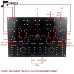
The tube sockets are linked directly to a PCB board of China manifacturing so, hoping they are designed good, I think that layout of Rg is OK like that. As to insert the 1K resistor properly I cut the pcb trace going to the input grid of the 12AT7 (lower section).
The output tubes are 6CA7 EH.
The tube sockets are linked directly to a PCB board of China manifacturing so, hoping they are designed good, I think that layout of Rg is OK like that. As to insert the 1K resistor properly I cut the pcb trace going to the input grid of the 12AT7 (lower section).
The output tubes are 6CA7 EH.
After having finally solved the problem covered by the thread by changing the place,emt of the toroidal transformer, I now find myself facing a new issue (to be honest I also had it at the beginning but temporarily put it on standby).
In practice this problem happens when I switch to UL mode.
In one of the two channels, on the speaker, with or without music I hear a whistle which I noticed changes in frequency in two ways: 1) by covering the 6CA7 with my hand the frequency of the noise is lowered, 2) this happens by also raising the volume on the potentiometer, the whistling decreases in intensity (but apparently not in frequency).
Then it occurred to me that during the building of the amplifier the (+) ot (-) wire accidentally disconnected at the speaker OUT hit the HV switch (Triode - UL selector) on the back of the chassis and I fear it damaged the power tube (even if the amplifier in triode mode has no problems and works well). Because that, maybe the delicate screen grid has broken.. As proof of this, by swapping the output tube on the other socket, the whistle goes to the other speaker.
Any idea anyway? Could it be as I think and possible solution?
Thank you
Never change the position of the Triode / UL switch when the amplifier is powered. Wait until B+ collapses, and the filaments and cathodes are cold, whichever comes first.
Changing the switch position will cause a very large transient voltage, that transient voltage might possibly destroy the output tube, might cause a short on the output transformer, or both.
The nature of the transient, is that most of the energy is high frequency. If the tweeter is connected, the possibility is low, but it might destroy the tweeter too.
Check for DCRs from B+ to UL tap, and from B+ to plate tap;
And for an Open from primary to secondary (should be infinite).
(disconnect the secondary Common from ground, to make the primary to secondary open test).
Check the method you used for the 1k grid stopper resistors. see (*) below
Note: 6CA7 pentode, and EL34 pentode require a tube socket connection from Pin 1 Suppressor Grid to Pin 8, Cathode.
The 6L6's Pin 1 is not connected to any internal element, so with the socket connected from Pin 1 to Pin 8, it still works OK, with, or without Pin 1 connected to Pin 8.
But if the PCB was wired for a 6L6, with no thought of using either a 6CA7 or an EL34, Pin 1 might not have a connection on the PCB
Always have Either a proper load resistor connected, Or a loudspeaker connected.
After all of the above is checked, you may need to get another pair of 6CA7.
They should work in either socket.
(*) The 1k grid stoppers need to be as close to g1 grid socket connection, the cut trace can be right next to the socket pin.
Putting the 1k further away reduces or cancels the effect of the grid stopper.
You are very close to enjoying many hours of music!
Have Fun!
Last edited:
Well, actually I never used the triode-UL switch with the amp on, aware of the risks.
Rather, it was an accident where an exposed terminal of the wire going to the speakers hit the high voltage HV and then I remember that the 6CA7 started to glow noticeably for a moment. From here I suspected the damage.
Both the OT, however, are fine, They have normal resistance values on the primary (and secondary also not shorted).
I think I'll have to change the faulty tube.
Regarding the PCB, it is already set up for the EL34 by default with pin 1 connected to pin 8 truough a track.
I have just one question that haunts me. Why the amp works normally when in triode but in UL start to whistle?
Shouldn't it not work either way?
Last edited:
Triode Mode has a low rp plate impedance at each of the plate ends of the primary.
That changes the impedance that the transformer parasitic L and parasitic C are seeing from the output tube plate/screens.
Triode wired is lower gain
Ultra Linear has a lower amount of plate to screen negative feedback.
The gain from g1 to plate is perhaps 2 to 3 times higher than triode wired mode.
The plate rp is perhaps 2 to 3 times higher than triode wired mode. The primary, an all the parasitic L and parasitic C, is driven from a higher impedance, rp.
Some transformers do not have real low leakage inductance from the UL tap to the plate tap, even though the UL tap is 25 to 50% of the total plate winding.
This may cause a phase shift from the plate to screen negative feedback of UL.
Phase shift, Resonance, and wrong phase feedback have been known to make an amplifier stage into an oscillator.
Perhaps the B+ connection cooked the screen, the screen wires heated expanded or collapsed. That would their distance towards either g1, or towards the plate.
That would change the tube parameters, Gm, rp, u, and u of g2 to g1.
Could that cause instability or oscillation . . . perhaps.
Yes, a 1k carbon composite (Bradley)Is there a grid stopper resistor at g2 ? I suspect a kind of oscillation.
Thanks for the explanation, I suspect could be one or both the factior you mentioned in your post.
I could first try changing the OT in the whislting channel, and see what iit happens, of course anyway I think I'll have to order another new pair of t6CA7.
I noticed another phenomen occurring during the noise (with no music playing): when I detached the (+) and (-) plugs wired to the not noisy speaker a sort of whine came out from the amplifier itself (resonating OT) but not viceversa that is if I detached the other channel's plugs the noise seemed to disappear.
It is a strange behaviour to me all this though it must be a precise cause, I think.
Never disconnect the load from the amplifier output.
A loudspeaker, or a load resistor should be connected at all times.
If you did not have any problems, you may if you run the amplifier without a load.
Not all amplifiers are the same; but do not test your amplifier this way.
A loudspeaker, or a load resistor should be connected at all times.
If you did not have any problems, you may if you run the amplifier without a load.
Not all amplifiers are the same; but do not test your amplifier this way.
Latest update: today, following what was posted above, I tried to invert the primaries going to tube plates of both output transformers and after restarting the amp the whistling disappeared.
So basically I was probably having an oscillation due to a phase shift, is that correct? Considering also that the amp is working with a NFB around 5%.
Taking into account that the OTs were made by me, it may be that I inadvertently reversed the direction of winding compared to the secondaries (even if I remembered the purple wire at the end and the yellow at the beginning of the bobbin).
Now I don't know if for both or just one, is there a simple way to establish it without physically opening each transformer...
Easy phase testing of an amplifier output transformer.
An un-powered amplifier is safest, If you are not familiar with safe live testing . . . do not do it.
And, most 10X scope probes, and most scope inputs (for both DC coupled, and for AC coupled) are only good for 300V.
Most amplifiers have more than 300V B+.
The service department is ready to re-build your scope input circuit, and send you a new set of probes too.
So . . .
with the amplifier un-powered, and un-plugged, (and with bleeder resistors, every amplifier needs those, safety first!).
Check that B+ has completely discharged.
You need a 1 kHz signal source, apply it to the transformer primary.
Connect a 2 channel scope,
Channel 1 Probe tip to the plate of the output tube and transformer primary lead,
Probe ground clip to the transformer B+ connection (center tap for push pull transformers).
Channel 2 probe tip to the 4, 8, or 16 Ohm tap.
Connect the probe ground clip to Common of the output secondary.
This is a signal generator at the primary, just a low power signal. Do not put a terminating resistor or speaker load on the output.
Look at the 2 scope traces, they are either in-phase, or one sine wave is upside down versus the other sine wave.
This can be done with a closed up amplifier.
After the power is off and the cord unplugged, and waiting for the B+ to discharge,
Pull out the output tube, and put a blank tube header in the tube socket.
You can apply the signal generator at the plate connection of the header.
The signal generator can connect to ground, chassis, those have a B+ filter cap from there to the B+ for the plate, and 1kHz will couple nicely through the B+ cap that is at ground and the other end at the transformer primary B+ connection.
Non-invasive testing is the safest.
For you.
For your scope.
$0.03
Used to be $0.02
Just like what happened to the price of eggs, milk, and gasoline.
Thank you for illustrating the procedure, simple and exhaustive.
When I have some time I will do this test.
PS: for what I learnt the connection of the tube anode should be done to the beginning of the primary winding (near to core) and the B+) and to the outer winding for B+
Now, if I don't remember the right primary orientation respect to secondaries (the test above doesn't tell me which wire is where) is it a problem to keep those primary wires "inverted" for the amp to work properly?
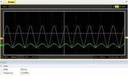
Hi, I made the measurement. Afer the primary wires of both OT being reversed (as I said above) the the sinewave seem to be on phase. No more whistle, even in ultralinear.
Here is the pic with the 1kHz injected signal. Channel 1 is connected to plate (+) and B+(gnd), channel 2 to 8Ohm output(+) and ground.
Here is the pic with the 1kHz injected signal. Channel 1 is connected to plate (+) and B+(gnd), channel 2 to 8Ohm output(+) and ground.
Attachments
Some common causes of hum . . .
As soulmerchant said: "The MOST common source of Hum is a Ground Loop".
The easier fixes of the causes of hum . . .
More filtering of B+
DC filaments on tubes that need that
Proper spacing and orientation of interstage and output transformers, versus power transformers and chokes
Non-magnetic chassis
All of the above do not fix a hum ground loop.
The hardest to investigate, and often hardest to fix cause of hum . . .
The hum ground loop.
"Grounds are commonly mis-understood".
All wires are resistors, and All wires are inductors.
Put current through a wire, and you have a voltage across it.
One end of a wire is Not common to the other end of the same wire.
I think magnetic coupling through chassis is over rated. I never built an amp with steel chassis, but I've owned a few. A Kodak Brownie 35mm projector amp and a Film-o-sound ditto stand out. Both extremely compact, high gain, steel chassis, PP, neither had chokes in the PI filter, yet neither had any audible hum while idle. Also curious to note, both had AC heaters for all tubes.
I agree, finding the causes of hum due to a ground loop is often difficult.
In my case from a modified PCB that I had to build around, I tried to keep the wiring in a certain order (separate power ground from signal ground) but a Chinese PCB is not great for improving on.
As for the case, be it wood or something else, I have always preferred for the aluminum top (also for workability reasons). I think the "bottleneck" is the size of the case, when I lacked with it I almost always had some issue: in this sense I was referring to magnetic coupling, the subject of the thread, when you have components that can interact being too close each other.
Attachments
- Home
- Amplifiers
- Tubes / Valves
- Supposed magnetic coupling with OTs