I'm not convinced it's magnetic coupling after seeing the wires inside the chassis. Could be a grounding issue too.

Your drawing:
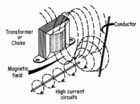
It looks to me that both the Choke, and the output transformer's core axis maximum radiation are vertical.
That is not a 90 degree relationship.
It looks to me that both the Choke, and the output transformer's core axis maximum radiation are vertical.
That is not a 90 degree relationship.
It looks to me that both the Choke, and the output transformer's core axis maximum radiation are vertical.
That is not a 90 degree relationship.
It's the power transformer that has the major magnetic influence here. My PSU circuit is input capacitor filtering :
If it was a choke input, it would have been very different : the choke would have radiated hum as nearly as the power transformer, and so the directions 1 of the choke and the output transformer would have indeed been incompatible.
T
tubelectron,
and all the other readers,
Schematics seldom show how things are really connected, in order to prevent hum ground loops.
Your secondary center tap needs to connect directly with as short as possible wire to the negative terminals of your two 100uF input caps.
That is the highest current, fastest rise, highest harmonic content, ground loop in the amplifier.
Do not connect the negatives of the two 100uF input caps to the amplifier central ground point.
Instead, connect from that point to the negative of the 500uF cap that is just after the choke.
Only then, from the negative of the 500uF cap connect another wire to the central ground loop.
That method Locally controls the main hum ground loop as best as is possible, from getting into the rest of the amplifier circuitry.
The next point of attacking hum, has to do with the method of wiring grounds of the input connector to the cathode circuit of the input stage.
Depending on the signal source grounds, it usually is best to insulate the input RCA connector grounds from the chassis, and instead connect to the bottom of the input tubes cathode circuitry.
the idea is to create many well controlled Local ground loops.
The "central ground point" has the job of connecting all the individually well controlled local ground loops together at a single point which also includes the chassis ground.
Again, just a method that works for me.
Last edited:
I tend to use toroid power transformers that are rated at least twice the draw they will see. The Antek units are not bad especially for the price. They also sell metal shielding for them which gives them a finished look as well. My chokes and output transformers are at 90* to each other and the toroid is on another axis. This has worked for me so far. I keep seeing one of my college professors makin a fist with his right hand and his index finger pointed straight and thumb pointed up saying “right hand rule“ for the direction of all the different fields! Prof Carter was a character!
Thanks tubelectron and 6A3sUMMER fot the hints,
I had already spotted this company online... it has a good number of components (transformers) but I haven't bought anything from them yet. I have to take it into consideration...
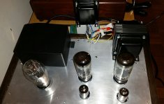
Now I've unscrewed the central OT and I'm starting to test it "by ear" by changing its orientation. Maybe I'll also try to do some measurements with USB scope (it's not high-level, it's Hantek 6022BE) and see what the result is
I had already spotted this company online... it has a good number of components (transformers) but I haven't bought anything from them yet. I have to take it into consideration...
Now I've unscrewed the central OT and I'm starting to test it "by ear" by changing its orientation. Maybe I'll also try to do some measurements with USB scope (it's not high-level, it's Hantek 6022BE) and see what the result is
...In case of a toroid mains transformer, the flux belt principle could be tried on the output transformers...
.
Please, could you explain to me better on how consisits this principle? Or you refer to a metal strip wound around the doughnut...
Right!tend to use toroid power transformers that are rated at least twice the draw they will see
And it cost more than normal
It is incredible how some people look for the quality of the amp then leave basic aspect just to save little money
Here in Italy we have good little company that work on trafos
Walter
An user referring to my wirings inside the chassis figured a possibile hum induced by ground loop: this is likely though every time I try to do linkings well according to a proper method I learnt.
Anyway I noticed a mistake committed by myself, that is to create a short link beetween the artificial ground from the 2 rect. diodes to the first filter capacitor (47uF) and also with the following ones (150uF), in a star ground style.
The main problem though is that I rely on a PCB board from Aliexpress (modified then by myself in order to work as an SRPP) having the star ground on the center of the board, and where converge both Power Ground and Signal Ground.
I made some modification inside but I can't say if it is enough.
https://it.aliexpress.com/item/4000550485271.html
As for the choke, I even tried rotating it by 90 deg but nothing has chance (maybe I should place it outside the chassis)
If you have a scope check if the hum is 50 or 100 Hz.As for the choke, I even tried rotating it by 90 deg but nothing has chance (maybe I should place it outside the chassis)
First of all
Then you can do something more.
A part of the poor cabling mainly for the input route you can short on board the input then give power one channel at time and check the noise
Walter
No, it is a closed (short circuit) copper strip around the output transformer. It should be outside the iron pack. I attach a photo of my amplifier.Please, could you explain to me better on how consisits this principle? Or you refer to a metal strip wound ...
https://photos.app.goo.gl/M99uTocKB6MW4CUH6
Thanks.
Indeed, I didn't know this trick of shielding the OT too. I plan to make it.
Waltube, I agree with yoi...checking the frequency it's a priority before stepping further.
Indeed, I didn't know this trick of shielding the OT too. I plan to make it.
Waltube, I agree with yoi...checking the frequency it's a priority before stepping further.
I.ll try to raise PT over chassis first. Put a book under to raise it couple of mm to see if do a difference. Sometimes get same problem with toroids...
Picture 1, OT outside the chassis plane -> very low hum level like other channel
Picture 2, OT rotated of 90 deg. facing the toroidal -> low hum but I can't say whether less than original orientation
Is this winding of the copper strip right? Sorry for not being so much smooth but it's adhesive (note also the OTs were both wound by me so they are somehow "handcrafted").
Picture 2, OT rotated of 90 deg. facing the toroidal -> low hum but I can't say whether less than original orientation
Is this winding of the copper strip right? Sorry for not being so much smooth but it's adhesive (note also the OTs were both wound by me so they are somehow "handcrafted").
Attachments

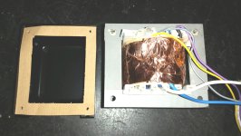
No! It is not correct. The copper strip (or band or belt) should be outside of the window. The outer side of the iron should also be wrapped, not only the bobbin. And it should be a true closed turn, adhesive copper strip is not good. I soldered the end of the copper to the beginning (with a little overlap) with a high power soldering iron. I found a good picture here:
https://www.diyaudio.com/community/...pose-effectiveness.284091/page-2#post-4555128
https://www.diyaudio.com/community/...pose-effectiveness.284091/page-2#post-4555128
I also found that a transformer generates mechanical vibration. Sensitive parts, like tubes tend to pick up this vibration, that propagates through the chassis. An elastic mounting spacer under the transformer could help.
You.re right. It have a turn in short.The flux band should be outer the iron.No! It is not correct. The copper strip (or band or belt) should be outside of the window. The outer side of the iron should also be wrapped, not only the bobbin. And it should be a true closed turn, adhesive copper strip is not good. I soldered the end of the copper to the beginning (with a little overlap) with a high power soldering iron. I found a good picture here:
https://www.diyaudio.com/community/...pose-effectiveness.284091/page-2#post-4555128
Thanks for reporting about the wrapping error. I saw the examples given...
From what I understand, the copper band must wrap exactly one complete turn around the transformer, in the way illustrated above, then soldered into the 360deg. junction. The inner side adhering on the laminations imust be insulated instead (I think something like a double coating of the V-66 spray).
The aim of all that would be to limit the leakage flux, interfering with the nearby transformer, rather than the magnetic flux itself. It's right?
I didn't understand where exactly the wire soldered to the strip should be then connected, I imagine to a screw anchored to the aluminum chassis.
However I will get some suitable copper foil for the job...
PS: I can't measure anything with the Hantek on the speaker outputs. I tried it with PC battery powered...what's wrong?
Attachments
Last edited:
- Home
- Amplifiers
- Tubes / Valves
- Supposed magnetic coupling with OTs