After hours of listening to this STC 6SN7+OPA541 amplifier, I find this to be a very good sounding one. My benchmark is a PLH (Nelson Pass' version of John Lindsey Hood class A) which I had been using for some years. As a matter of fact, I do prefer this STC-amp over the PLH. The dynamics is better, and you get a stronger sense of effortless in presenting the music. I do not have chances to listen to a SET for hours (cannot afford) so I cannot compare this to a SET. But nevertheless at US$150 built-cost this is certainly an amazing attempt. While there are many comments on this STC concept (as in this thread, and actually in many places in the internet), I would suggest you to build one to test.
if you have a 100 ohm resistor on the tube anode biased @ 4v = 40ma
8 - ~4v vgs on we get 4v / 100 = 40ma bias current through each half of pp transformer. if the idle current is higher more is needed.
changing any component values changes the baseline comparison of tubes vs transistors
8 - ~4v vgs on we get 4v / 100 = 40ma bias current through each half of pp transformer. if the idle current is higher more is needed.
changing any component values changes the baseline comparison of tubes vs transistors
Last edited:
Member
Joined 2009
Paid Member
Nice project and an imaginative topology. I like hybrids, lots of scope for something interesting!
Nothing daft going on here 😀
Nothing daft going on here 😀
I had some talks with another guy in another thread where a universal STC-was presented, accepting all kinds of power tubes.
Guess that's more of a breadbord design when trying different (odd) tubes with this special technology.
I see nothing stubid, or daft or whatever, maybe nerdish, to try out odd topologies.
It's my choice, ans even if the question is askes in here about "daft" designs, there's no reason to diss neither the design nor the person with the " daft". Oft course, a sligt disencoragement maybe, but being rude ....
When I was into British model railroading, the tru diyers hade a named for those being negative to almost everything - rivet counters. The guys sitting in the armchairs gobbling about the wrong number of spokes on the vans or too few rivets on a loco or whatever, and those guys never ever had built a sh*t.
But my last comment was OT, just show my feeling to crazy designs.
Guess that's more of a breadbord design when trying different (odd) tubes with this special technology.
I see nothing stubid, or daft or whatever, maybe nerdish, to try out odd topologies.

It's my choice, ans even if the question is askes in here about "daft" designs, there's no reason to diss neither the design nor the person with the " daft". Oft course, a sligt disencoragement maybe, but being rude ....

When I was into British model railroading, the tru diyers hade a named for those being negative to almost everything - rivet counters. The guys sitting in the armchairs gobbling about the wrong number of spokes on the vans or too few rivets on a loco or whatever, and those guys never ever had built a sh*t.
But my last comment was OT, just show my feeling to crazy designs.
My designs often look crazy, but because I follow end results by non-standard ways when I find better non-standard ways. It is not just a craziness per-se.
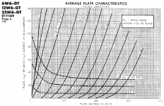
I know that this thread is a little old, but perhaps I can get a couple of questions answered. I like the 6SN7 but am obsessed with the 6W6GT. I’d make a computer with them if I could. Anyway, would it be possible to adapt this circuit to use a 6W6GT in triode running at around 25ma without too much trouble? If so, what alterations would you suggest?
Thank you for your help.
Link to the circuit:Super Triode Connected (STC) chip amp
Thank you for your help.
Link to the circuit:Super Triode Connected (STC) chip amp
Attachments
1. Increase CCS from 8mA to 25mA, 300R to 100RWould it be possible to adapt this circuit to use a 6W6GT in triode running at around 25ma without too much trouble? If so, what alterations would you suggest?
2. Decrease plate resistor to account for the higher Ip current
3. Increase Feedback coupling cap to account for lower output impedance.
IMHO, I would keep it at 6SN7, The change will result in a bigger NFB coupling cap. Not so sure it is for the better or the worst.
based on the info from TubeCAD, I built a super triode connected chip amp. <snip>
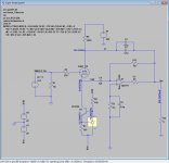
Hi FYC, I am very interested in your implementation. So, I quickly made a LTspice simulation. However, it seems that there is no so signal entering opamp's inverted input, can you confirm the feedback resistor and capacitor value for us?
Here attached are screenshots and LTSpice circuit files.
Attachments
Try R2 and R11 as 1 Megohm rather than 1 milliohm 😉
Damn! my silly mistake. Thanks tikiroo, after changing them into 1000k, things seems ok now 😀🙂
Hi Alllensoncanon,
Thank you for your reply. I know that that sticking with the 6SN7 makes more sense, but sometimes it's fun to be absurd.
I was considering using an LM317 on the cathode of the 6W6GT. I'm not sure how to calculate the feedback capacitor value. I didn't find anything on OPA541 datasheet. If you could point me in a general direction, I would be very grateful.
Thank you again
The LM317 is easy, it's the value of the feedback caps that I'm not sure about. You mentioned that I needed to change them to account for the lower output impedance. Do you have a recommendation for that?
Lets say you want to keep the same idle Vp. At 25mA, Rp needs to go from 3900R to 1200R or so. A 30uF should be close enough to keep the original intended freq response.
The STC or tube "triode emulation" scheme is certainly a practical approach to "SET" sound (with low output Z).
Some subtle points may be worth additional consideration. Using a current source through the tube, operates the tube on a horizontal load line, where Mu is nearly constant. So this is not -that- far from just using just a resistor for N Fdbk. Some (adjustable) loading on the tube cathode could tilt the load line slightly to provide more 2nd harmonic. Although that changes the amplifier gain too if overdone. (so limit the loading to a few % dist. range, with an adjustable knob for the listener)
No doubt some tube "purists" find the whole STC concept outrageous since it is mainly using SS power amplification and tube distortion. But nothing prevents this same idea being applied to an all tube power stage (likely P-P for power and low Z out). (inverted triode N Fdbk similarly applied at the front end)
Either using the inverted triode for the N Fdbk to the input stage, as in the STC, -OR- by using a pentode in the input stage of the tube amp, with the N Fdbk AC applied through the screen grid of the pentode. I have seen at least one schematic design on the Web that does this.
Just saying that you can do "triode emulation" with an all tube amp too (maybe using conventional "local" N feedbacks for the output stage to keep the power amp neutral ).
And such a design could be adapted to become a test analyzer to listen to the sound of any tube. (adjustable current through the test tube, and adjustable loading) Why not pick tubes for your designs (especially driver or outputs) that you like the sound of, rather than guessing from FFT traces or tube datasheet curves.
Last edited:
Hi FYC, I am very interested in your implementation. So, I quickly made a LTspice simulation. However, it seems that there is no so signal entering opamp's inverted input, can you confirm the feedback resistor and capacitor value for us?
Here attached are screenshots and LTSpice circuit files.
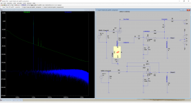
i think this schema is nonsense. if you want tube sound-then tube must be doing majority of gain... follower has gain <1 ... and GFB to anode is waste, because triode with medium or even high mu, will effectively "ignore" small signal injected to anode circuit.
so if you remove tube, and short the g-k it will sound same
6AL5 in feedback should be better for this effect box. Just play with filament voltage from 3 to 7 Volt according to your taste.
That's interesting. I just simulate a comparison and here is the result.😀i think this schema is nonsense. if you want tube sound-then tube must be doing majority of gain... follower has gain <1 ... and GFB to anode is waste, because triode with medium or even high mu, will effectively "ignore" small signal injected to anode circuit.
so if you remove tube, and short the g-k it will sound same
Attachments
- Home
- Amplifiers
- Tubes / Valves
- Super Triode Connected (STC) chip amp


