You are using an out of date browser. It may not display this or other websites correctly.
You should upgrade or use an alternative browser.
You should upgrade or use an alternative browser.
Super Regulator
- Thread starter Jason
- Start date
@jan.didden I’m doing modification of my audio LAN switch Netgear GS105. Inside there are two DC-DC converters 1.1V and 3.3V. I’m also replacing cheap clock to OCXO, so need good regulators to make everything sense.
You do understand of course that this is about high frequency digital network streams, not audio.
So it will do nothing for your audio.
The network does not transport audio as a voltage or current. It transports it as a code.
As long as the code is correct it will be turned in audio correctly.
It's like I write down a telephone number for you, and you tell me how large I should write the numbers and on which color of paper.
It will not have any impact on the number, as long as you can read it.
But it's your money. Good luck,
Jan
Last edited:
The network does not transport audio as a voltage or current. It transports it as a code.
As long as the code is correct it will be turned in audio correctly.
Phase-lock loops, hi-rez ADC's, voltage controlled oscillators, etc. require low noise. A poor (or ineptly) designed SMPS may have peak voltages sufficient to "trick" an ADC. I think this is what Wenzel Associates related in their discussion of RF supply lines.
It may be simpler to use an LT3045 with 2nV/RtHz noise @10kHz. LT3045 is adjustable down to "0" Volts with a minimum Vin of 2V.
The beauty of the SR is that it doesn't put a lot of harmonics back on the supply lines, unlike, for instance an LM317. It's all in the error amplifier and circuitry layout.
@jan.didden I thought similarly a few years ago until I heard the difference in many blind tests. Streamer and devices around it often have poorly designed power supplies, even expensive devices with external linear power supplies have a dozen or so DC-DC converters inside (e.g. Lumin streamers).
@jackinnj the solution with LT3042 or LT3045 is of course known and the simplest, but I would like to make it more ambitious 🙂
@jackinnj the solution with LT3042 or LT3045 is of course known and the simplest, but I would like to make it more ambitious 🙂
Nice low noise reference, why not just use that and a BUF634A.Hi,
Do you think it's possible to modify this circuit for 1.1V output ? I found ADR510 1V reference, but I'm not sure it will be ok.
Thank you for any advices.
I have a pair of these, well the original Old Colony/TAA versions but essentially the same. This version does have the opamp power input coming before the pass transistor, but I drive these regulators from pre-regulators. I want to be able to Enable/Disable their output in order to permit sequential power application and removal in my DAC. Has anyone done this with this regulator?
I have been able to come pretty close by switching in and out 1K resistors in parallel with C9 and C10 (on the diyAudio super regulator schematic). The shutdown and startup seem reliable and switching in brings the output down to under 2V under no load quickly enough, which is fine for my purposes (under 5V when disabled makes it "safe").
I have been able to come pretty close by switching in and out 1K resistors in parallel with C9 and C10 (on the diyAudio super regulator schematic). The shutdown and startup seem reliable and switching in brings the output down to under 2V under no load quickly enough, which is fine for my purposes (under 5V when disabled makes it "safe").
Last edited:
I would short the reference to ground to disable. You can even use an RC to gradually bring it up or down.
Jan
Jan
Thank Jan. It look like the combo of the 499r0 and 120uf downstream to the opamp + input produces a 250ms shutdown when shorting the LM329... And a disabled output of 1.8V, with an AD797 opamp. The enable is a bit longer, but the sequencing isnt a problem on startup, only shutdown where the outputs of these regulators are supposed to be off before the +5V feeding the DAC chip goes down. I can "tune" the shutdown of the 5V some using filter caps of the regulated 9V feeding the 5V regulators.I would short the reference to ground to disable. You can even use an RC to gradually bring it up or down.
Last edited:
Yes, good point, you would need an opamp with zero output capability.
I guess another limitation to using this approach is how safe (for the opamp) it is to pull the opamp input voltages to the + or - supply rails and if there is either a chance of damage to the opamp or lockup. The datasheet for the 797 shows its absolute max ratings for common mode DC input to be the supply rails so it is probably safe from failure. Another opamp I plan to bench test in this is the LME49710HA, once they arrive. Its datasheet's absolute max table appears to allow the input common mode DC to exceed the supply rail by .7V, if I read it correctly. In both cases the operational input range is 2V below the rails, so I wouldnt expect either to be trying to act as an error amplifier until I allow the + input to come back toward the reference voltage by removing the short across the LM329. So far, in my testing with the positive regulator I havent seen the opamp lock up or circuit refuse to start back up. I havent done the same with the negative regulator yet, but I dont see why it would behave differently. Neither opamp device seems to be particularly prone to lockup based on input voltages, if my web search is to be believed.
These typical audio opamps may survive R-R I/O but will not work with rail to rail I/O.
You need to select a R-R I/O opamp, they are available from the usual suspects, just go through their selection process.
IIRC the AD308X series would do.
Jan
You need to select a R-R I/O opamp, they are available from the usual suspects, just go through their selection process.
IIRC the AD308X series would do.
Jan
Correct. For this situation, I dont need them to function as an error amp with inputs at the rails, just not self destruct or lock-up.
Well they need to function down to 0 volt. 0 volt out is no special mode.
Jan
Jan
If I needed the regulator output to go to zero volts when disabled, then I would need to look at using opamps with rail-to-rail input/output. The AD797 gets me under 2V (with the 2 samples I have in the regulators I get to 1.8V in the positive regulator and -1.5V in the negative) which are about where the datasheets say the limits of the common mode inputs are supposed to be. My reason for wanting to enable/disable the outputs in a timely manner is related to a cautionary note in the AK4499EX literature that states damage to the DAC outputs could result if the analog 5V power inputs are removed before or applied after the +/-15V I/V opamp power is removed or applied.
My +/-15V for the opamps is derived from a dedicated torroid thru a pair of LM317 that produce +/-18V (pre-regulator) then to the Jung-Didden super-regulator.
The rest of the power is from a dedicated torroid that produces a raw voltage for the DAC circuits and a raw voltage (from the other secondary) for the USB to I2S controller and Arduino display controller thru switching regulators that have enable/disable controls in order to allow me to hold off startup of the USB and display micros until the DAC is up. For the DAC board,I use 3 stages of regulation for the analog 5V. First, a switching regulator (mostly to sallow me to control the enable/disable, if need be) which is set at 15V, then a LM317 set at 9V. That is sent to the DAC board where four separate "analog side" regulators produce 5V for the analog portion of the 4499 and two 5V retgulators that feed five 1.2, 1.8 and 3.3 volt regulators for the digital portion of the 4499, plus the AK4191 and a microcontroller used to set parameters of the 4497 and 4191.
Both torroids are powered on thru the same switch, a nd obviously power off thru that or when power is removed from the unit externally.
I have a fairly simple timing circuit that controls when each power supply is enabled after AC power on and issues a disable whenever AC power is detected to have been removed. That is the main purpose of the switching regulators. There is no switching regulatore in the power path of the +/-15V supply and given the level of power filtering and dual regulation, the +/-15V is slow to turn on compared to the 5V :analog" voltage, but slow to turn off as well. So being able to disable - or get the +/-15V under 5V before the "analog" 5V drops out is the goal of this exercise. Getting it quickly to under 2V works very well with the method you suggested. Under normal power up circumstances, in my unit, the 9V supply will already have booted up and removed the short around the LM329 before the super-regulator even gets usable input from the pre-regulator. It is the disable/shutdown part that really needed the quick response, and I have that now.
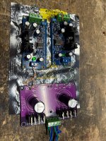
I finally got my super regulators going after 4 years of holding onto the boards. I am thinking I want to build a Pass Front End with this PSU or the BA3 Front end, so I am looking for correct parts for 24V+-.
Here is what I have now:
I am seeing approx. 24V on the outputs with 26.5V input. I plan to increase the input voltage by getting a slightly larger transformer, but I wanted to first see if I should make any changes to my Zener or my opamp. I saw somewhere a 10V zener is better for 24V.
I have some OPA1611 I can use which I saw were recommended over the AD817.
Thank you.
Here is what I have now:
- 6.9V Zener
- AD 817 opamp
- R7 - 1k
- R16 - 100 ohm
- R6 - 2.4k
I am seeing approx. 24V on the outputs with 26.5V input. I plan to increase the input voltage by getting a slightly larger transformer, but I wanted to first see if I should make any changes to my Zener or my opamp. I saw somewhere a 10V zener is better for 24V.
I have some OPA1611 I can use which I saw were recommended over the AD817.
Thank you.
Attachments

AD817 is a bit noisier than the AD848 Walt used in the seminal articles from 1995 (15nV/RtHz vs 5nV/RtHz). In the final analysis it should work fine. While AD797 tests best, it can break into oscillation if you look at it cross-wise.
I have used LME49710 with great results.
BTW, you are "gaining up" the noise of the Zener diode. Analog Devices webstore had a few pieces of LM329 in stock. Use www.findchips.com search engine.
I have used LME49710 with great results.
BTW, you are "gaining up" the noise of the Zener diode. Analog Devices webstore had a few pieces of LM329 in stock. Use www.findchips.com search engine.
Last edited:
I just went through my parts draw and I have almost every part to go with a Wayne’s preamp with 18V+-
I think I’ll go this route to be safe, keep the 6.9V zeneer and use the opa1611.
Any issue with using 26.75V input to drop to 18V-20V with these parts?
I have a 20VAC dual secondary Antek I would like to use.
I think I’ll go this route to be safe, keep the 6.9V zeneer and use the opa1611.
Any issue with using 26.75V input to drop to 18V-20V with these parts?
I have a 20VAC dual secondary Antek I would like to use.
Be careful to place powered stuff on conducting bags ...I finally got my super regulators going after 4 years of holding onto the boards.
Jan