Their web pages talks about the company's "120V" technology (power supplies +/- 60VDC). This passage caught my eye:I didn't design this. Designed by a friend of mine who uses it in commercial products ( https://spl.audio/en/ ).
I'll ask about the ref. Their pride is a discrete opamp running off of +/-60VDC. These minisuperregs are set for 60V output.
Jan
And I'm wondering if there exists ANY DAC whose output level is +22 dBu at 0dBFS (?). Certainly I've never heard of such a thing. That's a sine wave with peaks at +13.8V and troughs at -13.8V. Which DACs are capable of this?Most audio devices work with an internal operating voltage of +/-15 volts and can thus process a maximum input level of +21.5 dBu. If a DAC, for example, has an output level of +22 dBu at 0 dBFS, level peaks of the music material would already cause overloads in the input stage of the device.
I just got my OKTO DAC8 Pro modified for 8Vrms because I needed a bit more gain. Higher values would be possible.
In theory, with +/-15V you could get 14V peak or so with smart design. Some opamps run at +/-18 or even +/-20 or 22.
These pro guys are crazy in an interesting way ;-)
Jan
In theory, with +/-15V you could get 14V peak or so with smart design. Some opamps run at +/-18 or even +/-20 or 22.
These pro guys are crazy in an interesting way ;-)
Jan
It's part of the 3-pin output connector.dispensed with sense too?
Jan
Hi. Everyone telling different things and I am confused. I have 10 empty boards and I have SMD lm4562 3pcs and dip lm4562 2pcs and dip ne5534 10pcs. And SMD opa627 8pcs. Which ones may be more suitable? I am not looking for something too good - ultra high end. Just want 3-5x better than lm317 may be ok for me.
Last edited:

I think ad817 is ok for me as I read they don't oscillate but I should buy them. Here my boards. I will use them for dual 15v typical active crossover boards or preamps and maybe 6/24 crossover and some for Jlh amps.Opamps are a bit expensive
Attachments
I just got my OKTO DAC8 Pro modified for 8Vrms because I needed a bit more gain. Higher values would be possible.
In theory, with +/-15V you could get 14V peak or so with smart design. Some opamps run at +/-18 or even +/-20 or 22.
These pro guys are crazy in an interesting way ;-)
If that's true then I find it misleading to claim "Most audio devices work with an internal operating voltage of +/-15 volts and can thus process a maximum input level of +21.5 dBu." Especially since Jensen + John Hardy have been selling discrete JE-990 opamps with ±24V power supplies to the professional audio market since 1980. So has Samuel Groner; I've attached a ±40V discrete opamp of his. The pro audio guys have had excellent alternatives to ±15V IC opamps for 45 years.
I think it would be far more honest to say "Most IC opamps use +/- 15V power supplies, which can create maximum input level limitations when connected to professional audio gear whose circuitry can run on ±24V power supplies or larger. Therefore we designed our own proprietary opamps using discrete devices, and chose to run them at ±60V supplies. This ensures compatibility with everything in the pro audio domain, and it also gives us something unique to boast about in sales literature."
Attachments
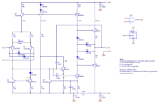
On the sense input of the Didden design there is a low pass filter to improve stability when remote sensing is used. I wonder why this works succesfully. The problem I see is that, analysing the open loop phase, the opamp causes a 90 degree phase lag, starting at a very low frequency. The input filter causes another phase lag which is 45 degrees at about 1.6 Mhz and increasing with frequency to another 90 degrees. So, even apart from any parasitic poles in the loop, the phase lag would come very close to 180 degress well within the bandwidth of the regulator, and hence I would expect this design to be unstable.
Clearly, it isn't. But I wonder why. I noticed that the compensation used by Walt Jung in the original article works differently. In that design the cap is shorting out the sense loop, which would seem better to me because it causes no additional phase lags.
I realise that Jan is aware of this and must have made a deliberate choice to change it. So, this is just me trying to learn something. Hope Jan, or anyone else who thoroughly understand the operation of the circuit, can elaborate.
Gary Galo decoupled the "sense" lines with 10R resistors in his article on hotting-up the Adcom GFP preamplifier.
Hi Jack, I think that was actually the article I was referring to. My mistake.
The cap in Jan's design reminds of of the old problem of a parasitic capacitance on the negative input of an opamp causing oscillation. What am I missing?
The cap in Jan's design reminds of of the old problem of a parasitic capacitance on the negative input of an opamp causing oscillation. What am I missing?
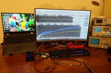
it is always and only about gain and phase margin. Phase margin can be lost in many ways / places ,in the loop of buffered amplification and comparison. The 100R resistor from early articles from Jan Didden and Walt Jung, with 100pF or so, can be also conveniently used for loop gain and phase measurements with Bode Plot analyzers and adequate high frequency transformer.
I use at least 4 to 6 resistors instead of potentiometer for exact voltage output setting, and to have some wiggle room in all directions, including optimum noise and dissipation. You can use the original 100R no problem, if you only know what it is doing to voltage divider thus voltage output, and what it does in RC filter, to the accumulated phase shift. I e.g. use this 100R still.
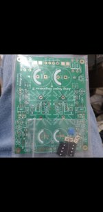
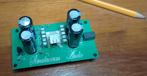
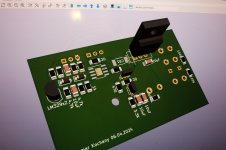
Here two photos of my earlier attempts, just for the eye joy and perhaps inspiration ;-)
I use at least 4 to 6 resistors instead of potentiometer for exact voltage output setting, and to have some wiggle room in all directions, including optimum noise and dissipation. You can use the original 100R no problem, if you only know what it is doing to voltage divider thus voltage output, and what it does in RC filter, to the accumulated phase shift. I e.g. use this 100R still.
Here two photos of my earlier attempts, just for the eye joy and perhaps inspiration ;-)
Attachments
Hi,
Do you think it's possible to modify this circuit for 1.1V output ? I found ADR510 1V reference, but I'm not sure it will be ok.
Thank you for any advices.
Do you think it's possible to modify this circuit for 1.1V output ? I found ADR510 1V reference, but I'm not sure it will be ok.
Thank you for any advices.
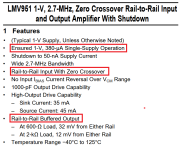
It should be possible in principle but I don't know if you can find an opamp that will run on 1.1V and accept 1V inputs.
That should be the first issue to solve.
Check the low voltage opamps at ADI and TI for instance, there may be some.
Of course you can always supply the opamp from the regulator input voltage whih can be much higher, for instance around 5V.
Jan
That should be the first issue to solve.
Check the low voltage opamps at ADI and TI for instance, there may be some.
Of course you can always supply the opamp from the regulator input voltage whih can be much higher, for instance around 5V.
Jan
That seems a good candidate Mark.
The relatively low bandwidth will limit performance up the freq scale, but it may be sufficient for the intended use.
@couguarek, what is the inteded use anyway? Just curious.
Jan
The relatively low bandwidth will limit performance up the freq scale, but it may be sufficient for the intended use.
@couguarek, what is the inteded use anyway? Just curious.
Jan
Last edited:
- Home
- The diyAudio Store
- Super Regulator