What are the feedback resistor values? Is 13.2V to be expected with a 6.1V reference?So managed to assemble + - 15 super regulator on a DIY shop boards, used all recommended components (AD825, lm329, R6 1100ohm). To test it I made linear power supply from 15V transformer it gives me 18-18.2V input to the super regulator. Regulator gives out 13,2V, I measure at the lm329 only 6.1V. Did I screw something up, or is 18V not enough? (in the dac I plan to put super regulator in it will get 25V)
The resistors that set the current into the ref are R5, R12, so you can calcute the current.
Another possible issue is the input ripple. If the low ripple points fall below the headroom, you get output ripple and thus lower average (as measured by your DMM) output voltage. What is the capacitor after the rectifiers?
If R5 and R12 are correct, and not by mistake 49.9k, you seem to have low LM329's.
Try to shunt R5 and R12 with, say, another 4.99k and see if the LM329 voltage rises.
Jan
Hi, R5 and R12 are 4.99K. I think my multimeter is off... Trying to check it on variuos DC and AC sources and everywhere it shows too little. Inside Dac after 5V regulator it shows 4.4V, on recharged battery to 4.1 it shows 3.7. So probably I will need to buy a new multimeter.What are the feedback resistor values? Is 13.2V to be expected with a 6.1V reference?
The resistors that set the current into the ref are R5, R12, so you can calcute the current.
Another possible issue is the input ripple. If the low ripple points fall below the headroom, you get output ripple and thus lower average (as measured by your DMM) output voltage. What is the capacitor after the rectifiers?
If R5 and R12 are correct, and not by mistake 49.9k, you seem to have low LM329's.
Try to shunt R5 and R12 with, say, another 4.99k and see if the LM329 voltage rises.
Jan

Jan, could you look into my other question about improved reference filter, I posted right after my first problem, post #2878. Thank You.
Yes those are the values. I'm not sure I remember that specific case, but in general, and in theory, increasing the R value would be beneficial.Question to Jan Didden. I read your article about improved reference filter for audio regulators (2021). You suggest raising resistor from 500 to 5k if capacitor is low esr and leakage. On diyAudio 2.3b boards that would be R4 and R11, C9 and C10?
The reference is supplied from the very stable and very noise-free output voltage, so would be rock-stable. The thing that those components do is filter the noise that the LM329 itself generates. The filter itself, in particular the capacitor (C9, C10) generates also noise, albeit very low.
If I look at the measurements jackinnj did in his Linear Audio article, these were based on the original values and there's nothing left to be desired.
So after all this waffling I should confess that I really don't know whether it is worthwhile or not. It certainly will not be audible from your amp one way or another. Can't make it any prettier ...
Jan
Hello good morning, I have a question.Perché usare LM4040-10 quando è molto peggio di LM329, con resistori 1720/705 ottieni 24 V o 1430/768 per 20 V e con LM329 che ha un rumore inferiore e un'impedenza dinamica inferiore rispetto a LM4040.
Nelle mie versioni 4A per Le Monstre utilizzo un LM329 a basso rumore migliorato e resistenze 1370/787 per +/-19V.
I tried to put into practice the suggestion given to me to have 24 vdc at the output.
I just replaced R6 and R13= 1.72Kohm and R7 and R14= 705ohm without changing anything else...and hoping I understood.
Superreg.. powered with 24vdc, output from Superreg..23.9/24 VDC!!!!
Sounds perfect, but here comes the question,...why don't the two LEDs light up?? I can't figure out where I'm wrong.
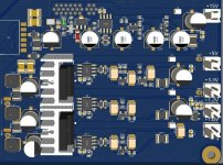
PS: sorry for the color of the cables but I'm doing some tests.. yellow at V+ of BA3, blue at GROUND of BA3, green at V- of BA3, and power is external, out of the chassis.
Thanks again!!
PS1: Before being used (supereg) I used it on another BA3 and everything worked including the LEDs.😵😵
Last edited:
Your resistor values are correct (if you use LM329).
But you cannot get 24V out with 24V in, there is no regulation.
Either increase Vin to 27 or 28V or lower Vout to 20 or 21V.
Jan
But you cannot get 24V out with 24V in, there is no regulation.
Either increase Vin to 27 or 28V or lower Vout to 20 or 21V.
Jan
Ok, I understand, I'll try to set the input voltage at 28 vdc right away.Your resistor values are correct (if you use LM329).
But you cannot get 24V out with 24V in, there is no regulation.
Either increase Vin to 27 or 28V or lower Vout to 20 or 21V.
Jan
Thanks, I'll let you know the results.
Ok, I understand, I'll try to set the input voltage at 28 vdc right away.
Thanks, I'll let you know the results.
Okay, set 28 vdc, perfect sound good and LED!!!Your resistor values are correct (if you use LM329).
But you cannot get 24V out with 24V in, there is no regulation.
Either increase Vin to 27 or 28V or lower Vout to 20 or 21V.
Jan
Thanks a lot Jan
I am planning to use this superregulator to try upgrade power supply to mark levinson 360 dac analog boards, with 15v and 5v. So maybe decreased noise could be beneficial. For 15V I am using LM329, for 5V I was planning on using ADR525 or GLED431 as suggested by Grunf. GLED431 has very low noise, but as I understand it has a bit more fluctuation (thermal?) so it might give 5V output fluctuations and I am afraid that can fry PCM1704 dac chips as they are quite sensitive.Yes those are the values. I'm not sure I remember that specific case, but in general, and in theory, increasing the R value would be beneficial.
The reference is supplied from the very stable and very noise-free output voltage, so would be rock-stable. The thing that those components do is filter the noise that the LM329 itself generates. The filter itself, in particular the capacitor (C9, C10) generates also noise, albeit very low.
If I look at the measurements jackinnj did in his Linear Audio article, these were based on the original values and there's nothing left to be desired.
So after all this waffling I should confess that I really don't know whether it is worthwhile or not. It certainly will not be audible from your amp one way or another. Can't make it any prettier ...
Jan
If I try to increase R4 to 5k, how low would you suggest C9 esr should be? I was planning to use in all C positions panasonic FC 220uf 63V which has esr of 0.13, I could put nichikon kz 100uf 50v with esr of 0.08 or even panasonic FR 220-470 with esr of 0.03.
So my guess was right, my multimeter was faulty. Got another multimeter and it measured 14.6V at the output, had to combine a few resistors to increase R6 from 1070 to 1170, that gave output 15.2, tomorrow I will try try to get R6 to 1150 that should give just a bit over 15V. Does superregulator output decreases a bit with applied load?So managed to assemble + - 15 super regulator on a DIY shop boards, used all recommended components (AD825, lm329, R6 1100ohm). To test it I made linear power supply from 15V transformer it gives me 18-18.2V input to the super regulator. Regulator gives out 13,2V, I measure at the lm329 only 6.1V. Did I screw something up, or is 18V not enough? (in the dac I plan to put super regulator in it will get 25V)
I used GLED431 for +/-5V for my PCM1702 and there were no problems, the voltage change caused by thermal drift was not big and ranged in tens of mV. Btw, KZ(UKZ) is the best choice.I am planning to use this superregulator to try upgrade power supply to mark levinson 360 dac analog boards, with 15v and 5v. So maybe decreased noise could be beneficial. For 15V I am using LM329, for 5V I was planning on using ADR525 or GLED431 as suggested by Grunf. GLED431 has very low noise, but as I understand it has a bit more fluctuation (thermal?) so it might give 5V output fluctuations and I am afraid that can fry PCM1704 dac chips as they are quite sensitive.
If I try to increase R4 to 5k, how low would you suggest C9 esr should be? I was planning to use in all C positions panasonic FC 220uf 63V which has esr of 0.13, I could put nichikon kz 100uf 50v with esr of 0.08 or even panasonic FR 220-470 with esr of 0.03.
Thank you for the answer, that assured me to try gled431. I managed to get all the needed parts for gled431, as I understand there are just 3 parts: ltl4231n green led, ztx 951 and 150R rezistor? I will try UKZ in that position. Also You advised to put UKZ in C3 and C7 positions as these and C9, C10 are the most crucial?I used GLED431 for +/-5V for my PCM1702 and there were no problems, the voltage change caused by thermal drift was not big and ranged in tens of mV. Btw, KZ(UKZ) is the best choice.
A regulator's purpose in life is to prevent output voltage droop with load. Hence the name regulator ...Does superregulator output decreases a bit with applied load?
Also note that it is totally waste of time and effort to try to get the 15+ at exactly 15.000V.
BTW Good catch on the faulty multimeter.
Jan
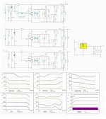
I don't know how important phase is here but I have paid special attention to phase, can't get better than this. What I have learned is low esr caps at the input and at the output gives worst phase response so I have added optimal resistor 330 ohm to in-out condensers which have esr as you can see 50m, that gaved me ok phase. Additional inductors at the input and also at the output gives me almost ideal phase. This is TinaTI simulated circuit which I'm going to try on real pcb. +15V above is supply only for opams, an small reg, and the rest is supply for digital circuity, if succed it will be main supply for my next direct digital audio amplifier 🙂
Attachments
Last edited:
You can put UKZ for both position , for C9,10 and C3,C7 .Thank you for the answer, that assured me to try gled431. I managed to get all the needed parts for gled431, as I understand there are just 3 parts: ltl4231n green led, ztx 951 and 150R rezistor? I will try UKZ in that position. Also You advised to put UKZ in C3 and C7 positions as these and C9, C10 are the most crucial?
If you can't get the ZTX951 you have another schematic on Walt's site with 2N3906 and 2N2222.
I'm not sure but it looks like better than simple resistor divider? Found psrr about 3db better@savan I don't understand the role of jfet CCS, isn't there a much better position to use it?
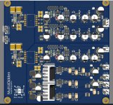
This one I have made isolated but newer built, since flybuck regulators from Maximum chosed here is for 10W maximum I will remove them and will make an test pcb soon in relation to post 2895 and will post it here when I finish pcb design. This one looked promissing but sadly for 10W only, my waste of time designing them 🙁 Dimension 110x110
Edit:
it will be probably ~70x70 like picture 2
Edit:
it will be probably ~70x70 like picture 2
Attachments
Last edited:
- Home
- The diyAudio Store
- Super Regulator