Success! It is fixed and working. For anyone who runs into this issue, I put a 100nF caps in the C11 and C12 positions instead of 100pF caps. It did not like that AT ALL. Mistake on my part.
LF squegging. In hindsight, it all falls into place.
Well done, you persevered and solved it, chapeau.
Jan
Well done, you persevered and solved it, chapeau.
Jan
I also learned ALOT about the circuit trying to troubleshoot it. What is the recommended current for the CCS? I've got 2.3mA across the LED. I know it is somewhat tied to the load. I'm expecting 100mA or less load.
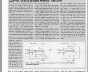
What is important is the current that the current source can deliver to the pass device.
With a pass transistor Hfe conservatively at 100, and Iout 100mA, the max base current required is 1mA.
But if you don't want to cut it close, set the cs current at say 5mA. That is measured by measuring the voltage across the cs emitter resistor.
Divide that by the Re value and you've gort the current. Ohms Law and all that.
The current through the LED should be more than the required base current for the cs transistor.
2.3mA through the LED is fine.
Jan
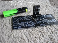
Thanks! Pcb above is replacement for audio transformators on DSC2 dac, with success, for the first time I had few volts dropuot and a bit hot regs so I needed to add predregulators to get 17V first and its ok now, stable 🙂
Last edited:
With the super regulator is it better to leave the PSU ground floating or connected to earth? If to earth I suppose this would take place at the Super Regulator output ground? (The chassis - a Galaxy - is itself earthed at the incoming mains connection (220/230V line)).
Note: As the regulator has two ground outputs I've just linked them across at the output as the PCB the PSU is supplying has just the standard 3 input terminal -ve/0V/+ve
Note: As the regulator has two ground outputs I've just linked them across at the output as the PCB the PSU is supplying has just the standard 3 input terminal -ve/0V/+ve
The psu ground (gnd output of the supperreg) is connected to signal ground automagically when you connect it to the circuit. That's all the ground that is needed - anything more will cause ground loops.
The chassis can be connected to protective Earth from the mains but that is totally separate from any signal or supply ground.
Look at the psu output ground and signal ground as just another net, nothing special.
Jan
The chassis can be connected to protective Earth from the mains but that is totally separate from any signal or supply ground.
Look at the psu output ground and signal ground as just another net, nothing special.
Jan
Thanks Jan.
I've seen some PSU topologies where safety ground and signal ground are connected - hence the confusion.
I've seen some PSU topologies where safety ground and signal ground are connected - hence the confusion.
So managed to assemble + - 15 super regulator on a DIY shop boards, used all recommended components (AD825, lm329, R6 1100ohm). To test it I made linear power supply from 15V transformer it gives me 18-18.2V input to the super regulator. Regulator gives out 13,2V, I measure at the lm329 only 6.1V. Did I screw something up, or is 18V not enough? (in the dac I plan to put super regulator in it will get 25V)
Question to Jan Didden. I read your article about improved reference filter for audio regulators (2021). You suggest raising resistor from 500 to 5k if capacitor is low esr and leakage. On diyAudio 2.3b boards that would be R4 and R11, C9 and C10?
Do you have the sense lines hooked up? If just testing the regulator, you need to run a wire from each sense terminal to each output terminal, + to +, - to -.So managed to assemble + - 15 super regulator on a DIY shop boards, used all recommended components (AD825, lm329, R6 1100ohm). To test it I made linear power supply from 15V transformer it gives me 18-18.2V input to the super regulator. Regulator gives out 13,2V, I measure at the lm329 only 6.1V. Did I screw something up, or is 18V not enough? (in the dac I plan to put super regulator in it will get 25V)
Yes, I have. Just had another thought and will test it tomorrow. My Multimeter might be faulty 😒. It is good UNI-T meter, but just checked AC, and it gives just 198V instead of 220V. Also 15V transformer with rectifier should give at least 20-22V and not 18, so Superregulator might be working good, just my meter is off...Do you have the sense lines hooked up? If just testing the regulator, you need to run a wire from each sense terminal to each output terminal, + to +, - to -.
- Home
- The diyAudio Store
- Super Regulator