Here is a question.
We understand that there should be no low ESR caps at the load. Let us assume that the load has 5 x 22uF medium to high ESR low ESL electrolytic caps from a power plane to a ground plane for the purpose of local low inductance path for the power supply. The 22uF caps would cause no problems. But the power plane and ground plane would have a parallel plate capacitance from 30pF to 100pF, depending on the PCB power and ground plane sizes. Would this parallel plate capacitance cause problems to the SR?
I don't have any ideas about the "ESR" of the power and ground plane capacitance so I don't know the answer.
Good thinking. Personally, I don't think it would be a problem but I haven't investigated it. First, the value is most probably too low to cause issues, and secondly there is some 'isolating' inductance between the SR and the load. The problem with too low ESR is anyway only for caps directly at the SR.
Jan
As long as the heatsink is floating, not connected to anything, I never do it.
I do use some grease or a thermal rubber sheet to aid heat transfer.
Jan
I do use some grease or a thermal rubber sheet to aid heat transfer.
Jan
Here is a question.
We understand that there should be no low ESR caps at the load. Let us assume that the load has 5 x 22uF medium to high ESR low ESL electrolytic caps from a power plane to a ground plane for the purpose of local low inductance path for the power supply. The 22uF caps would cause no problems. But the power plane and ground plane would have a parallel plate capacitance from 30pF to 100pF, depending on the PCB power and ground plane sizes. Would this parallel plate capacitance cause problems to the SR?
I don't have any ideas about the "ESR" of the power and ground plane capacitance so I don't know the answer.
Don't worry. Just use reactance calculator, something like this: http://www.electronics2000.co.uk/calc/reactance-calculator.php
100pF @ 100MHz will give you 15.9R and capacitor's own ESR is way lower and can be neglected.
And super regulator will run out of steam (gain) looong before that 😀
Last edited:
Don't worry. Just use reactance calculator, something like this: http://www.electronics2000.co.uk/calc/reactance-calculator.php
100pF @ 100MHz will give you 15.9R and capacitor's own ESR is way lower and can be neglected.
And super regulator will run out of steam (gain) looong before that 😀
Thanks. At what frequency does the SR run out of steam?
A related question is, how much capacitive load can the SR stand before runs out of phase margin? We know there is a medium to high ESR 100uF at the output of the SR. But I don't know if another 100uF or so capacitance at the load would cause problem or not. It has been saying that 100uF as the load. What I am not sure is that if that 100uF refers to the output capacitor or the capacitance at the load (which means 200uF altogether).
Should C4 and C8 capacitors be the worst quality unbranded high ESR junk ?
What is the optimal ESR for the output capacitor? Has this ever been published?
You could add 0r1 to increase the effective ESR, if you discover than the stability margins are a bit low giving ripple on the supply lines.
A related question is, how much capacitive load can the SR stand before runs out of phase margin?
The phase margin requires a minimum capacitance and ESR. 100uF with at least 0.1 ohms as Andrew suggested seems to work reliably.
The max is limited by inrush currents and such.
Jan
As long as the heatsink is floating, not connected to anything, I never do it.
I do use some grease or a thermal rubber sheet to aid heat transfer.
Jan[/QUOTE
Thermal rubber sheets are insulators which in fact degrade heat transfer between device and heatsink. adding about 0.4C/W thermal resistance, acting as using smaller radiator.
Thin layer of thermal grease improves heat transfer.
ALL insulators add thermal resistance, one more than the other. Whether any material, be it grease or rubber or whatever, decreases or improves total heat transfer depends on what it was without it. A not very flat heatsink coupled to not very flat heat tabs on a device can benefit from a material that fills the void.
Grease fills that better but rubber is much less messy than grease so if the situation allows it, it's a nice solution.
Jan
Silicone rubber pads are more practical replacement for mica+thermal grease insulators.But for direct transistor to heatsink mounting, grease,which is itself insulator, in thin layer ,reduces thermal resistance. The same with heatsink bracket/heatsink interface.Silicone pads here degrade performance, and even direct contact is better.
All in all rubber insulators and thermal grease have different application.
Rubber insulators are slightly worse equivalent of mica washers and thermal grease combination, only where electrical conduction is not desirable.
All in all rubber insulators and thermal grease have different application.
Rubber insulators are slightly worse equivalent of mica washers and thermal grease combination, only where electrical conduction is not desirable.
I built +/-30V SR to power my Xono phono preamp. I tested it with OPA604 op-amp, but I have also AD817, LME 49710, AD 825, OPA134 and NE 5534 .
Which is the most suitable for low noise application as in my case? For headphone amp higher noise AD 815 is probably the best .Output voltage is rock solid even with NE5534. Aries pin headers are very practical for SMD/DIP adapters.
Which is the most suitable for low noise application as in my case? For headphone amp higher noise AD 815 is probably the best .Output voltage is rock solid even with NE5534. Aries pin headers are very practical for SMD/DIP adapters.
You should look for the noise performance of the opamp since it's their noise which sets the regulator noise level.
LME 49710 is the lowest noise but bjt input is probably more sensitive to RFI than j-fet input OPA 604.
Does it mean that usual AD825 and AD 817 versions are not targeted to ultra low noise MC phono preamps?
Does it mean that usual AD825 and AD 817 versions are not targeted to ultra low noise MC phono preamps?
Guys, cold you please tell me what is the difference between v2.2 and v2.0?
2.2 has the option to us SOIC08 SMD opamps, the 2.0 only DIL08. No functional difference.
Jan
Wiring and Grounding
Hi there,
I am trying to build my first diy project.
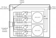
I read a lot but I am still not sure how to do the wiring and grounding - especially when using the super regulators. My best guess so far is depicted in the images below.
I would like to use four superregs (SR) (2 x pos and 2 x negative power supplies).
Could you guy please help me with my remaining questions:
1. Grounding that avoid potential ground loop problems
- Does it make sense to connect the input ground the potentiometer and to the chassis?
- Is it possible to connect the headphone jack GND as depicted?
- Does the potentiometer GND L / R connected to the superregs make any sense?
- Will the grounding in picture 1 work?
2. Unregulated DC
- I am not sure if I should use 2 x 1,000uF capacitors before SR?
I highly appreciate your comments.
Kind regards
Michael
Hi there,
I am trying to build my first diy project.
I read a lot but I am still not sure how to do the wiring and grounding - especially when using the super regulators. My best guess so far is depicted in the images below.
I would like to use four superregs (SR) (2 x pos and 2 x negative power supplies).
Could you guy please help me with my remaining questions:
1. Grounding that avoid potential ground loop problems
- Does it make sense to connect the input ground the potentiometer and to the chassis?
- Is it possible to connect the headphone jack GND as depicted?
- Does the potentiometer GND L / R connected to the superregs make any sense?
- Will the grounding in picture 1 work?
2. Unregulated DC
- I am not sure if I should use 2 x 1,000uF capacitors before SR?
I highly appreciate your comments.
Kind regards
Michael
Attachments
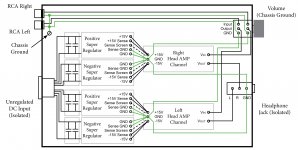
the volume potentiometer is part of the signal input circuit.Does it make sense to connect the input ground the potentiometer and to the chassis?
It is NOT part of the Chassis.
The input socket has two wires. Those two wires feed the vol pot.
The vol pot has two output wires. Those two wires feed the two input pads of the mono PCB.
If the vol pot has a metal body, or a metal securing thread, then that metal should be connected to chassis.
Your right hand diagram is wrong.
You have connected the input RCAs to Chassis. Remove this connection.
You have connected the vol pots to Power Zero Volts. Remove this connection.
Last edited:
the volume potentiometer is part of the signal input circuit.
It is NOT part of the Chassis.
[snip]
Your right hand diagram is wrong.
You have connected the input RCAs to Chassis. Remove this connection.
You have connected the vol pots to Power Zero Volts. Remove this connection.
Indeed, fully agree.
Otherwise, the raw DC routing is spot on.
an
- Home
- The diyAudio Store
- Super Regulator