you are right for the AD825 running at 24V per rail should not have problems + - 15V = 30V total
Jan, is this modification correct for 24V output?
MOD FOR OUTPUT +- 24V
LM329 = VRef. 6.9V
24V – 6.9V = 17.1
17.1/6.9 = 2,478260869565217
R7 - R14 = 1K
R6 - 13 = 1K * *2,478260869565217 = 2K478
OR
R7 – R14 = 2k
R6 – R13 = 2K * *2,478260869565217 = 4k956
Perfect!. But don't get hung up on absolute accuracy, that 6.9V is nominal and can vary a bit.
But of course that 24V need not be 0.1% either.
Jan
Which is the correct way to handle Kelvin connections, as recommended for the superregulator? Which is the best point to connect the wires to on the unit to be powered?
That is rather easy to guess when you have a single IC to power, but when you have two opamps or where the circuit is discrete, which is the best point to connect the wires to?
That is rather easy to guess when you have a single IC to power, but when you have two opamps or where the circuit is discrete, which is the best point to connect the wires to?
I have got LM329 with 7.15 V at the most, never under 6.9 V but you could expect 6.6-7.25 V if you read the datasheet....that 6.9V is nominal and can vary a bit....
Which is the correct way to handle Kelvin connections, as recommended for the superregulator? Which is the best point to connect the wires to on the unit to be powered?
That is rather easy to guess when you have a single IC to power, but when you have two opamps or where the circuit is discrete, which is the best point to connect the wires to?
Good question. Try to identify that part of the circuit that is most sensitive to the supply. It often is the first stage of the preamp or whatever.
Jan
Jund Didden PCB layout review
Hello,
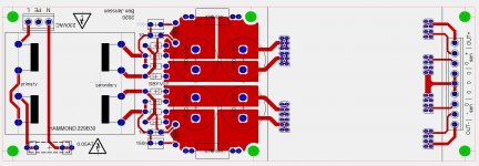
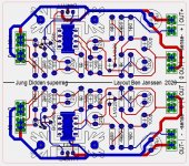
I've just finished the layout version1 of my preamp PSU with a Jung Didden superreg which can be assembled using pin headers.
I've followed the original schematic, except for the input electrolytic. As the superreg PCB is direct after the main cap's, I assume this cap has not any added value.
I connected the 0's of both the pos and neg superreg's to each other on the PSU PCB. This to create a ground start point.
Or would it be better to add the 0's together on the preamp (buffer) PCB?
Have a look here to understand what I'm willing to do.
https://www.diyaudio.com/forums/pow...erstanding-star-grounding-69.html#post6136959
Regards
Hello,
I've just finished the layout version1 of my preamp PSU with a Jung Didden superreg which can be assembled using pin headers.
I've followed the original schematic, except for the input electrolytic. As the superreg PCB is direct after the main cap's, I assume this cap has not any added value.
I connected the 0's of both the pos and neg superreg's to each other on the PSU PCB. This to create a ground start point.
Or would it be better to add the 0's together on the preamp (buffer) PCB?
Have a look here to understand what I'm willing to do.
https://www.diyaudio.com/forums/pow...erstanding-star-grounding-69.html#post6136959
Regards
Attachments
Last edited:
Good afternoon Jan, I need to make a superregulator in smd version, please tell me, can I replace panasonic fc with x7r ceramic capacitors with a lower nominal value?
Good afternoon Jan, I need to make a superregulator in smd version, please tell me, can I replace panasonic fc with x7r ceramic capacitors with a lower nominal value?
The actual X7R capacity varies considerably from its nominal value. Very much depending on voltage, temperature etc, sometimes can vary a factor of 4.
I would not use it, or, if I must, heavily over design.
If possible use C0G caps but I know they are not available in high values.
If you want to build an SMD unit, you could use SMD electrolytics of course.
Jan
Thanks Jan, I know that the values of x7r\x5r actually depending on temperature and voltage, does the capacitance change, but does tantalum work?
I need to make the regulator as compact as possible.
I need to make the regulator as compact as possible.
Dag Jan,
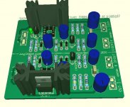
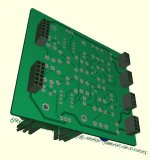
Regarding post 1847, do you see any problems with the superreg layout?
For example, I connected the heatsink to ground and added a small ground plane underneeth the opamp.
All comments are welcome.
Groeten
Regarding post 1847, do you see any problems with the superreg layout?
For example, I connected the heatsink to ground and added a small ground plane underneeth the opamp.
All comments are welcome.
Groeten
I gave my design to diyaudio to help them cover the cost of the forum. My recommendation would be to use the PCB from the diyaudio store and support this great place.
Jan
Jan
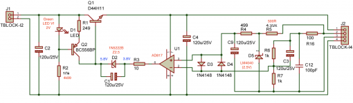
5V Regulator Current
Dear Jan,
I've built up a few of your regs using the DIY audio PCB in +5V form. Good news is that it works outputting a stable 5.24V. My issue and question relates to output current. I'm seeking up to 1A output but as soon as the reg hits around 750mA the output voltage collapses.
I've attached the circuit diagram with my 5V component modifications shown in red. I've also indicated the voltages across the zener at the output of the opamp when it's regulating at around 600mA. When the current draw increases I see the opamp output rise to around 4.2V but the other side of the zener only increases to 5.9V? (I expected to see 2.5V across the zener)
Wondering if it's something to do with Q2 not providing enough base current to Q1??
Your guidance would be much appreciated!
Best regards,
Bruce
Attachments
You can try to increase the current source a bit.
An easy fix is to replace the pass transistor with a Darlington. You need a bit more input/output difference, and check the heatsinking, but 1A+ should be easy.
In your case, all current from the current source goes into the pass device, and the opamp basically stops sinking current, which means there is no or almost no current through the zener, thus the lower voltage.
Jan
Last edited:
Appreciate your tips - thanks!
My reckoning is that the current source is set for (2-0.70)/249 = about 5mA. Looking at the data sheet the BC556B can do Ic 100mA continuous - so lots of headroom?
So would see you any harm in going for say 100R source resistor == 13mA source current?
Bruce
My reckoning is that the current source is set for (2-0.70)/249 = about 5mA. Looking at the data sheet the BC556B can do Ic 100mA continuous - so lots of headroom?
So would see you any harm in going for say 100R source resistor == 13mA source current?
Bruce
Don't forget that the opamp must be able to absorb all of the current source current to regulate at light loads. So don't overdo it, maybe double it, that should give you enough headroom.
Jan
Jan
Tried 10mA and that was marginal.
After looking at the BC556B and AD817 data sheet I've increased the current source current to 20mA as that's well below the +-50mA source / sink rating of the opamp and my load will be constant around 500mA.
Works great now! 2.5V across the zener and stable.
thanks for your assistance,
Bruce
After looking at the BC556B and AD817 data sheet I've increased the current source current to 20mA as that's well below the +-50mA source / sink rating of the opamp and my load will be constant around 500mA.
Works great now! 2.5V across the zener and stable.
thanks for your assistance,
Bruce
- Home
- The diyAudio Store
- Super Regulator