Hi,
I am confused about maximum output volume.
I read it was depend on max. Op Amp Voltage.
The OPA is connected to ground, so I have to calculate the voltage x2?
For example a AD825 is +-15V max.
Can this OPA run with 30V to ground max?
Minus 5V Headroom >> 25V Output?
Thanks
Daniel
I am confused about maximum output volume.
I read it was depend on max. Op Amp Voltage.
The OPA is connected to ground, so I have to calculate the voltage x2?
For example a AD825 is +-15V max.
Can this OPA run with 30V to ground max?
Minus 5V Headroom >> 25V Output?
Thanks
Daniel
Yes. The OPA doesn't know about ground. It only knows about the voltage between V+ and V-. If that stays below 30V, all is fine.
That's what the data sheet will say: max between V+ and V- is 30V. How you divide that up depends on your application. Most use +15 and -15, but that is just to get max output signal level.
Jan
That's what the data sheet will say: max between V+ and V- is 30V. How you divide that up depends on your application. Most use +15 and -15, but that is just to get max output signal level.
Jan
Perfect! Thanks.
So I can build a +-22V Supply with two AD825.
Daniel
Depends what you mean by 'a +-22V supply'. If two separate units, with each opamp total supply 22V, yes.
Jan
Hi guys,
my name is Simon, I am 31 years old and living in vienna. I am reading here in this forum for a long time but actually never did a diy-project by my self. Maybe I will start with the super regulator. It should power my RME Adi-2 Dac. In stock it has a +12V 2A power supply. The manual says that it should be at least 1A. But I don`t need the negative voltage. Can I joint the outputs of the two regs so to say in parallel to get a higher current? I would use a transformator with separate secondaries and link i like this: PosVOut from positive board to +dc from dac and return to -dc from dac. NegVOut from negative board to -dc from dac and return to +dc from dac.
Greets,
Simon
I mean just like in the attach.
The sense pins must be connected to the voltage nodes -- this will lower the output impedance of the SR as you are not screwed up with the resistance of the connecting wires.
I mean just like in the attach.
Very interesting idea but it will not work I'm afraid. The two voltage will never be exactly the same. Even a few mV difference will cause large currents to flow from one supply to the other.
If the max is 1A, I would use just a pos SR, with the series pass device replaced by a Darlington transistor.
Also check the dissipation (1A x (input-output voltage difference) for heatsinking.
Jan
Hy Jan,
thanks for your answer. Can you suggest any Darlington transistor? Super reg and transformator get its own case, so I could mount the transistors sideplates.
Simon
thanks for your answer. Can you suggest any Darlington transistor? Super reg and transformator get its own case, so I could mount the transistors sideplates.
Simon
Okey, I will use the TIP122. I will also build the negative side, but just for fun. So the pnp type should be TIP127?
Do I need some more changes in design? I will use the bom list from diyaudiostore.com. Excluding the resistors that divide the output voltage.
Simon
Do I need some more changes in design? I will use the bom list from diyaudiostore.com. Excluding the resistors that divide the output voltage.
Simon
Modifications to get stabilized +- 24V output
Jan, could you tell me what modifications I should make to get stabilized + -24v output.
I want to use the super regulator to power the BA-3 front end.
regards.
Jan, could you tell me what modifications I should make to get stabilized + -24v output.
I want to use the super regulator to power the BA-3 front end.
regards.
You use the voltage drop over the LED so the only thing you should be aware about is that the minimum input voltage to the regulator will be increased if you use a blue or white LED. All other colours will produce 1.6 to 2 volts.The green LED can be any green LED or an specific brand and model?
Jan, could you tell me what modifications I should make to get stabilized + -24v output.
I want to use the super regulator to power the BA-3 front end.
regards.
If you use the 6.9V reference as in the article, to set Vout to 24V you need to adjust the ratio of the two feedback resistors at the neg input. They should provide also 6.9V with 24V at the output.
The other thing is that the zener in series with the opamp output should be nominally 12V or thereabouts (anything between 5V and 20V will work, the idea is to keep the opamp in its working range).
Jan
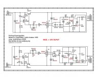
Jan, is this modification correct for 24V output?
MOD FOR OUTPUT +- 24V
LM329 = VRef. 6.9V
24V – 6.9V = 17.1
17.1/6.9 = 2,478260869565217
R7 - R14 = 1K
R6 - 13 = 1K * *2,478260869565217 = 2K478
OR
R7 – R14 = 2k
R6 – R13 = 2K * *2,478260869565217 = 4k956
MOD FOR OUTPUT +- 24V
LM329 = VRef. 6.9V
24V – 6.9V = 17.1
17.1/6.9 = 2,478260869565217
R7 - R14 = 1K
R6 - 13 = 1K * *2,478260869565217 = 2K478
OR
R7 – R14 = 2k
R6 – R13 = 2K * *2,478260869565217 = 4k956
Attachments
- Home
- The diyAudio Store
- Super Regulator