I don't think noise is a big problem since the design has a rather heavy noise filter after the reference. We see also that the major noise source is the opamp itself, even when a LT1028 or an AD797 is used. We can see from jackinnj's measurements how clear this is.You can also buy 1.2V and 2.5V reference diodes. I don't know how LEDs perform noise wise compared to dedicated ref diodes though. Anyone know that?
Jan
The drawback of using LED's as voltage reference is the poor stability versus temperature and different current.
You can also buy 1.2V and 2.5V reference diodes. I don't know how LEDs perform noise wise compared to dedicated ref diodes though. Anyone know that?
Jan
here are a set of measurements:
http://www.diyaudio.com/forums/part...eds-zener-diodes.html?perpage=10&pagenumber=1
red LED operate at around 1.7V or so with a few mA, if i recall correctly, so it may be the ticket for 3.3V or so, as far as voltage goes anyway.
A green LED+317 gives a good 3.3V regulator.
Fine adjustment using the out to adj resistor value.
i haven't thought about using an LED....good idea.
...albeit low frequency Zout is already pretty good with the suggested bypass 10uF.
Where lm317 suffers seems to be in higher frequencies in that regard, and one needs to heavy bias the IC to lower the overall Zout significantly, as per datasheet.
But it does sound pretty good overall indeed (i tried it recently in my digital gear).
If you look at the datasheet from LT6200 (which is specified at 3V), the plain 6200 performs as well as AD797 in Open loop gain at higher frequencies, and the lt6200-10 has 20 dB more OLG.
Maybe there are better opamps for low voltage duty, i havent search really...
Unfortunately 1.25V from the 317 plus either 1.2V, or 2.5V, don't arrive at 3.3V
2.05V + 1.25V = 3.3V
It is certainly not a "super regulator", more a good enough for most purposes.
From memory of some tests posted here, I thnk the lower voltage LEDs are quieter than the poorer voltage references. But I believe there are some that have lower noise than others.
I think my remark was for the opamp regs, nost specifically the 317, but you are right of course.
Jan
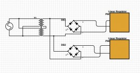
I have noticed in the pictures posted the +/- rails are on separate transformer windings is this a necessity?
it can be center tap if you have a negative and a positive supply you want to connect togheter for + and -.
if you want to connect two positive or two negative supply togheter for + and , you need 2 sets of sperate secondaries.
Look around the net for exemples...plenty of them
Change the adjust cap from 10uF to 100uF.i haven't thought about using an LED....good idea.
...albeit low frequency Zout is already pretty good with the suggested bypass 10uF.
Where lm317 suffers seems to be in higher frequencies in that regard, and one needs to heavy bias the IC to lower the overall Zout significantly, as per datasheet...............
For effective HF response, use local decoupling at each digital current consumer.
Look at any competent digital board. It is riddled with local decoupling.
Look at any competent smps. It is riddled with R+C snubbers
For auxiliaries, I have used Zeners in the gnd leg of a 7805 to give the voltage I did not have in stock.
I have also used a Zener instead of the lower resistor in a 317. The LED just gives a lower noise lower voltage reference for the adjust pin.
A 317+resistor+LED gave very close to 3.3V. I still have that in my drawer.
Last edited:
Here is a diagram of how i have it wired up. I forgot to mention that i had c8 polarity reversed so i replaced it with a new cap in the correct polarity, could this have damaged something else in the supply?
... but of course if you now connect a + from one supply to a - of the other you short out the bridges. You do see that, right?
Jan
I built my second Jung/Didden Super Reg.
I did a very stupid thing yesterday. When testing it, I forgot to connect it to a rectified DC stage but put AC out of the transformer (18V-0-18V) directly to the inputs of SR!
C2 and C6 were obviously damaged. I have not had time to check the parts or to test them again.
Have I lost the whole SR? Can I repair it? Which parts are likely damaged?
Last edited:
I built my second Jung/Didden Super Reg.
I did a very stupid thing yesterday. When testing it, I forgot to connect it to a rectified DC stage but put AC out of the transformer (18V-0-18V) directly to the inputs of SR!
C2 and C6 were obviously damaged. I have not had time to check the parts or to test them again.
Have I lost the whole SR? Can I repair it? Which parts are likely damaged?
i personally would change every piece that has 3 or more "legs" as well s all the caps that can't stand up the rating.
then you can test them separately for salvages.
maybe other people have more clues...?
The opamp NEEDS local decoupling.
That could be in addition to the CRC, or it can incorporate the C of the CRC on the PCB.
I would make the CRC off board.
Then use the recommended local decoupling on board.
That could be in addition to the CRC, or it can incorporate the C of the CRC on the PCB.
I would make the CRC off board.
Then use the recommended local decoupling on board.
Hello,
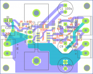
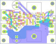
I've layed out an SMT board (49x39mm) for 10V@50mA duty
Flip D1 180 degrees.
Depending on the input voltage, you might be able to get away with pouring copper instead of using a heatsink -- in this case you can use an SMT pass transistor.
The opamp should NOT be decoupled on the SR. Reasons why are in the original 1995 articles.
Normally you are correct but this can end up in heavy oscillation.The opamp NEEDS local decoupling.
Normally you are correct but this can end up in heavy oscillation.
I respectfully disagree.
You can also buy 1.2V and 2.5V reference diodes. I don't know how LEDs perform noise wise compared to dedicated ref diodes though. Anyone know that?
Jan
i have published some measurements in
< #73341 >
< #75214 > of that blowtorch thread in the lounge.
I will write them up more nicely when I find the time.
Now that there is the LT3042, it is no longer that important.
regards, Gerhard
Last edited:
Hm, I believe it is already correct (notice the cathode notch on the silkscreen).Flip D1 180 degrees.
Perhaps AndrewT meant that the opamp needs local decoupling of the whole circuit, i.e. 120uF C2? I've replaced it with a 2.2uF film cap in series with a 100mR resistor to get more HF attenuation, just in case the snubber on the bridge+filter board passes some of it through. The bridge+filter board will be ~2cm away, so I was hoping that extra ~20mR (from connectors) and ~15nF won't make much difference compared to the ESR/ESL of the last capacitor in the filter.Normally you are correct but this can end up in heavy oscillation.
- Home
- The diyAudio Store
- Super Regulator