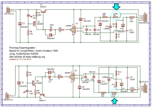
For those who are thinking about building their own customized version of a Super Regulator, which does NOT use the diyAudio Store PCB . . . . AND which happens to output a voltage Vout_reg that is at least 4.5 volts greater than Vref . . . . then my little experiment yesterday might be of interest. I'm fooling around with preliminary ideas for a Super Regulator that outputs Vout_reg = 15.0 volts and uses a Vref around 7 volts. Since (15 - 7) is comfortably greater than 4.5 volts, yesterday's experiment is applicable to my situation.
However I realize that many builders want a Super Regulator with output voltage waaaaay less than 15 volts, and therefore (Vout - Vref) is waaaay less than 4.5 volts. So the little contrivance shown here is not useful for them and I am very sorry.
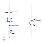
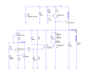
Figures 1 and 2 (attached below) show the basic idea. Resistors R5 and R12 on the official Store schematic, provide bias current to the super excellent Zeners-On-Steroids D5 and D10. I plan to replace R5 and R12 (on a custom PCB not the Store PCB) with constant current sources. Indeed, with cascoded constant current sources.
I built the Figure 1 circuit on a protoboard, and connected a potentiometer in the R1 position. Then I dialled the knob up and down until the current was 3 milliamps. It happened to require 260 ohms for this particular J113 JFET; no doubt other J113's will require different resistances than 260 ohms to give 3 mA. That's an annoying reality of cheap analog switch JFETs like the J113 -- their analog properties vary dramatically. Fortunately I had two 130 ohm resistors in my box, so with them in series I was able to achieve 260 ohms. That gave 3 mA for this particular J113.
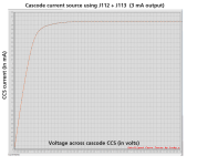
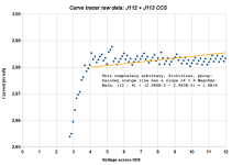
When I attached the Figure 1 circuit to the "Locky Z Curve Tracer" I got the plot in Figure 3. The trace is just a single J113 current source below ~ 4 volts on the plot. Then the magic of cascoding takes over, the J112 starts to help out, and suddenly the plot goes flatline above ~ 4 volts.
The LockyZ curve tracer can barf out its measured data as an ascii text file, so I did that and slurped the X,Y datapoints into a spreadsheet. That produced the plot in Figure 4. It's just like Figure 3 except we're not using LockyZ's hard-to-reconfigure plot software any more; now we're using a spreadsheet. Again you can see the single-JFET-only current source behavior below ~ 4 volts, transitioning to J112+J113 cascode current source above 4 volts.
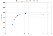
Zooming in the plot view, we get Figure 5. Zooming in even more, we get Figure 6. It's plain and evident that the DACs and ADCs inside the LockyZ Curve Tracer do not have unlimited precision - - - but still, the shape of the plot tells a story. And it's a happy story.
Figure 7 is the same as Figure 6 except I have drawn a straight line among the measured data, deliberately exaggerating the slope (output impedance) of the data. It's a conservative under-estimate of the output impedance of this cascoded current source. I encourage others to draw their own straight line upon Figure 6 and calculate their own slope (output impedance). It will be fun!
Conclusion: by replacing one component (4.99K resistor R5) with a three component CCS, I was able to increase the impedance of the Vref bias network by a factor of 320. (math: 1.6E6 / 5E3 = 320). This increases isolation between the regulated output and the Vref; it also opens the door to using different Vref components which may not be as good as the venerable but expensive LM329. Ahem.
_
However I realize that many builders want a Super Regulator with output voltage waaaaay less than 15 volts, and therefore (Vout - Vref) is waaaay less than 4.5 volts. So the little contrivance shown here is not useful for them and I am very sorry.
Figures 1 and 2 (attached below) show the basic idea. Resistors R5 and R12 on the official Store schematic, provide bias current to the super excellent Zeners-On-Steroids D5 and D10. I plan to replace R5 and R12 (on a custom PCB not the Store PCB) with constant current sources. Indeed, with cascoded constant current sources.
I built the Figure 1 circuit on a protoboard, and connected a potentiometer in the R1 position. Then I dialled the knob up and down until the current was 3 milliamps. It happened to require 260 ohms for this particular J113 JFET; no doubt other J113's will require different resistances than 260 ohms to give 3 mA. That's an annoying reality of cheap analog switch JFETs like the J113 -- their analog properties vary dramatically. Fortunately I had two 130 ohm resistors in my box, so with them in series I was able to achieve 260 ohms. That gave 3 mA for this particular J113.
When I attached the Figure 1 circuit to the "Locky Z Curve Tracer" I got the plot in Figure 3. The trace is just a single J113 current source below ~ 4 volts on the plot. Then the magic of cascoding takes over, the J112 starts to help out, and suddenly the plot goes flatline above ~ 4 volts.
The LockyZ curve tracer can barf out its measured data as an ascii text file, so I did that and slurped the X,Y datapoints into a spreadsheet. That produced the plot in Figure 4. It's just like Figure 3 except we're not using LockyZ's hard-to-reconfigure plot software any more; now we're using a spreadsheet. Again you can see the single-JFET-only current source behavior below ~ 4 volts, transitioning to J112+J113 cascode current source above 4 volts.
Zooming in the plot view, we get Figure 5. Zooming in even more, we get Figure 6. It's plain and evident that the DACs and ADCs inside the LockyZ Curve Tracer do not have unlimited precision - - - but still, the shape of the plot tells a story. And it's a happy story.
Figure 7 is the same as Figure 6 except I have drawn a straight line among the measured data, deliberately exaggerating the slope (output impedance) of the data. It's a conservative under-estimate of the output impedance of this cascoded current source. I encourage others to draw their own straight line upon Figure 6 and calculate their own slope (output impedance). It will be fun!
Conclusion: by replacing one component (4.99K resistor R5) with a three component CCS, I was able to increase the impedance of the Vref bias network by a factor of 320. (math: 1.6E6 / 5E3 = 320). This increases isolation between the regulated output and the Vref; it also opens the door to using different Vref components which may not be as good as the venerable but expensive LM329. Ahem.
_
Attachments


The prices, ouch! I bought a bag of 100 from DK a century ago at a fraction of that price. There are other regulators from ADI with better noise and drift stats -- but not TO92 (and you'll learn the pleasure of soldering MSSOP).Good news: Linear Technology's implementation of the LM329 voltage reference IC, is in stock at Mouser and DigiKey and Farnell and Newark. Walt Jung's original design for the Super Regulator uses two LM329s; one for the positive regulated output and one for the negative regulated output.
Not such great news: they're expensive! Octopart chart attached below.
_
Hello all,
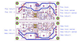
If I am targeting +9-0-9V from super regulator I plan to build and had some query on the input side. Can I short the pos return and neg return pins on the input of super regulator board? Since the final connection will have a common "zero" or ground, I think it should be ok but wanted someone to confirm the same. Please let me know.
See the attached picture for reference.
Thanks
Balaji
Attachments
Hello everyone, I am considering making up one of these for an ALLO USBridge.
However the current draw on boot up is 3A and then running steady state of 240mA in use, any ideas if you could get away with a short spell of over current or if there is a way of using parallel boards to take the current demand?
Thanks!
Rich
However the current draw on boot up is 3A and then running steady state of 240mA in use, any ideas if you could get away with a short spell of over current or if there is a way of using parallel boards to take the current demand?
Thanks!
Rich
Rich - SuperRegulator's are great but only good for up to 1 amp.
If I had a USBridge I would use this:
Don't be intimidated by it being SMT. The designer has made it super easy to build for people like me who dislike
working with SMT.
For the DAC you connect to the USBridge, maybe use a SuperREG for that.
If your DAC is USB powered only, you could use another AMYALICE for that by making up a USB Cable with an AMYALICE spliced in to the
5V on the cable
If I had a USBridge I would use this:
AmyAlice: DC filter for SMPS, using 2 feedthru capacitors + SMD assembly. max 3A & max 48V
from over on the Power Supply Threads. It has improved the sound on everything I have used it on so far.Don't be intimidated by it being SMT. The designer has made it super easy to build for people like me who dislike
working with SMT.
For the DAC you connect to the USBridge, maybe use a SuperREG for that.
If your DAC is USB powered only, you could use another AMYALICE for that by making up a USB Cable with an AMYALICE spliced in to the
5V on the cable

You'll get more accurate simulation results if you include the self-capacitance of the inductors and if you also include the self-inductance of the capacitors, in your simulation. It is a bit of a challenge to obtain these values but confident and self-reliant designers usually rise to the challenge.
Store filter PO89ZB: Rseries = 0.040 ohms // Lseries = 2.2 uH // Cparallel = 470uF
AmyAlice filter: Rseries = 0.100 ohms // Lseries = 10.0 uH // Cparallel = 470uF
Post #3,607 filter: Rseries = 0.200 ohms // Lseries = 2.2 uH // Cparallel = 470 uF << different from the other two >>
Store filter PO89ZB: Rseries = 0.040 ohms // Lseries = 2.2 uH // Cparallel = 470uF
AmyAlice filter: Rseries = 0.100 ohms // Lseries = 10.0 uH // Cparallel = 470uF
Post #3,607 filter: Rseries = 0.200 ohms // Lseries = 2.2 uH // Cparallel = 470 uF << different from the other two >>
So maybe I can help. I've been using the higher current version in my amplifiers for years. The problem is not high current at all, but rather dissipation. For 5V and 3A, the dissipation on the series transistor will be almost 10W. The scheme is from LTspice and there is a possibility that it will need to be adjusted a little in practice.Hello everyone, I am considering making up one of these for an ALLO USBridge.
However the current draw on boot up is 3A and then running steady state of 240mA in use, any ideas if you could get away with a short spell of over current or if there is a way of using parallel boards to take the current demand?
Thanks!
Rich
Attachments
@grunf I saw that you also used this pair 2SA1962 / 2SC5242 in your regulator. What are the differences between these two 2SC5200 and 2SC5242 for you to go for 2SC2542?
If I use this schematic with 1V ref then all the other parts could be still the same besides OP amp changed to ADA4625? For output 5V and 3A?
To use this regulator in class A amp then voltage ref changed to 6.8 or 10v and add up more diodes to D6, D7? Other changes needed do to have a 24V output?
If I use this schematic with 1V ref then all the other parts could be still the same besides OP amp changed to ADA4625? For output 5V and 3A?
To use this regulator in class A amp then voltage ref changed to 6.8 or 10v and add up more diodes to D6, D7? Other changes needed do to have a 24V output?
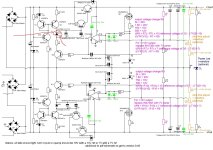
D4 and D6 in the schematic of post #3,611 (1N4739A) are DC level-shifters. They are included because the opamp cannot swing its output pin all the way to its supply rail voltages. In that circuit with the darlington pass transistor and the PNP emitter follower:
- You want Vzener < (RegulatedOutputVoltage - 5.0V) so the opamp's output pin is not required to swing impossibly low.
- You want Vzener > 1.2V so the opamp's output pin is not required to swing impossibly high
The only difference is in the packaging.@grunf I saw that you also used this pair 2SA1962 / 2SC5242 in your regulator. What are the differences between these two 2SC5200 and 2SC5242 for you to go for 2SC2542?
In that case some values should be corrected, points 4 and 5 can be connected together or inserted between the LDO reg that Walt Jung described in his last article. D5 is now a zener diode from 2.2V to 2.7V 1W.If I use this schematic with 1V ref then all the other parts could be still the same besides OP amp changed to ADA4625? For output 5V and 3A?
For 24V you have to add 3 more LEDs in series with D4, recalculate R6 and R7, D5 is now a zener 12V 1W, op amp is OPA1641, OPA828, ADA4625,AD825 or similar.To use this regulator in class A amp then voltage ref changed to 6.8 or 10v and add up more diodes to D6, D7? Other changes needed do to have a 24V output?
Attachments
Thanks for the suggestion!So maybe I can help. I've been using the higher current version in my amplifiers for years. The problem is not high current at all, but rather dissipation. For 5V and 3A, the dissipation on the series transistor will be almost 10W. The scheme is from LTspice and there is a possibility that it will need to be adjusted a little in practice.
Does this fit on the same Super Reg PCB, the circuit is hard to reConcile with the one on the store
I am sorry if this has been asked before, but how do I alter which components to suit my application?
My need is +/- 9.7V for a RIAA preamp.
Thanks!
🙂 morten
My need is +/- 9.7V for a RIAA preamp.
Thanks!
🙂 morten
Hi Morten, have a look here: https://www.diyaudio.com/community/threads/super-regulator.247281/page-76#post-5282055
Thanks for this, what I did in the mean time was to purchase a cheap current meter off eBay as my DMM was not reading current, and found out that the real current draw is about 500mA on normal use and then only up to 1.3A on transient peaks for less than a second. So practically I think the 1A model will work fine?tonescout - you would have to make your own PCB for Grunf's schematic.
See this thread over in the Parts Forum:
Ordering PCBs online (using Gerber files): A walkthrough -- featuring the fab "JLCPCB"
This is going to sound like a really dumb question and I am sure the answer is buried in these 180 pages of posts but after a couple of days of occasional noodling and reading some very interesting content here I still don't know the answer.
For the supply into the Super Reg, I know there will be an over-voltage, but I am not sure of the input topology
What is the ripple allowed/advised, and can I just use a non-regulated simple CRC or CLC after the rectifier?
For the supply into the Super Reg, I know there will be an over-voltage, but I am not sure of the input topology
What is the ripple allowed/advised, and can I just use a non-regulated simple CRC or CLC after the rectifier?
- Home
- The diyAudio Store
- Super Regulator