Original article:LED diode is put the wrong way and is reverse biased, conducting no current. Rotate it 180°.
Attachments
You have some very weird measured voltages. I’ll assume that all measured values are with negative sign and there were no positive voltages measured in reference to the ground.The led was correct but I change it anyway with no luck.
First, LED diode has 21 V across and is apparently OK. That is possible only with wrong LED polarity or burned out LED.
At the same time, if at Q4 position (BC546) is correct transistor type or not burned out, R8 should have some 20V across and should be smoking hot.
That is not the case as you would notice that and voltage drop across R10 indicates very small current, so Q4 is not passing current.
Another problem is that if Q3 base is at -0,6V, you can’t have -20.2V output. Only if Q3 is short circuit burned.
I would first pull out LED diode, Q3 and Q4 and verify with multimeter that they are OK.
Schematic looks ok, but looks like you have done something wrong on pcb side. Did you using original pcb or you have made one? Double check polarity of the: led diode, zener, check opamp pin 2 and 3, capacitors polarity, check if you have drawn the pcb correctly...
Maybe a rerun of earlier comments, but here goes:Dear All,
I need some help to debug a Negative Superreg at -15V.
I build 3 regulators for a dac that need +5V, +15V and -15V.
The +5V and +15V work at the first power up, absolutely stable, but I am not able to make the -15V working.
I recheck all the components, I changed the BC546, the LM369, the Zener 6,8V that I have available.
I do not have the AD825 so I install a OPA1641 that I have from another project but the result is the same so I reinstalled the AD825
I am sure I miss something very simple and I aid to ask for help for a so simple board but I am stacked...
I power up the board with a lab PSU and the Vout is following any change on Vin with more or less 1V difference
I take some measurement on the board referred to GND
View attachment 1199999
Any support will be appreciate
Thanks and Regards,
Enrico
The base of Q4 cannot be -0.135 to ground, obviously, unless there is no voltage drop across R9.
Thus there is no current through R9, thus D6 is either disconnected/broken or wrong way around.
Remove the opamp and Q3 and fix the Q4 base voltage first.
And check that you really measured against ground; that's the top line in the drawing.
Jan
Thanks Jan and All for your replies,
The PCB is not the original from DIYAudio but I design myself long time ago exactly as Jan design with the exception of the ground plane.
I design myself first of all because I like to design pcbs and also because I was ordering other pcbs to pcbway and was easy and cheaper instead place the order to DIYAudio.
I am reading again the long thread and I understand that is not a good idea to create the ground plane at the bottow and I hope this is not the problem.
The positive rail have no issue and it's designed with the gound plane too.
I rechecked anyway the PCB point by point with the schematic and is fine, no mistakes here.
I dismounted the OP, Q3 and Q4. The led light up that's is fine, not reversed and not broken.
I checked Q3 and Q4 with DCA Pro from Peak and both are recognized and fine. I have anyway some spare
The only issue that I have is the opamp. I have no more AD825. The only opamp I have in the hands is the OPA1641. It's a good substitute or I have to order the AD825? I live in Vietnam and get some good part here is quite difficult...
@ Jan, I think you are right, probably I take the measurement from the GND of the PSU that actually for the board is the -DCin. Sorry about that 🙁
If you confirm that I can use the OPA1641 I will resolder the board and send back the correct measure.
Thanks again to everybody for your kind help. Really appreciate
Regards,
Enrico
Well done, that's progress. You can build it up with Q3 and Q4 without the opamp. The Vout should rise up to the max, a few 100mV below the input. But that will allow you to measure and see if all is well like the current source and the reference.
If that works out fine (post measurements here) you can plug in the opamp and see how that goes.
Don't do everything all at the same time because it's hard to diagnose in such a situation.
And don't worry about the groundplane, that's not a go/no-go factor.
Jan
If that works out fine (post measurements here) you can plug in the opamp and see how that goes.
Don't do everything all at the same time because it's hard to diagnose in such a situation.
And don't worry about the groundplane, that's not a go/no-go factor.
Jan
Last edited:
Arghhh... I found the stupid mistake!!!
I inverted the output pin 2 and 3 in the PCB, mean that when I bridge pins 1/2 and 3/4 for the test actually I was bridging 1/3 and 2/4.
I did recheck the board 2 times before asking for help but I miss it.
My sincere apologize to to waste your time...
Jan, you think that I can remount the AD825 or better I use a new OPA1641?
Sorry again guys...
Enrico
Well you were successful, that's great on a Monday morning ;-)
In fact you are right that those connections are not completely logical.
I could change them next time but then there would be two different boards around, adding to the confusion.
A rock and a hard place.
Opamps are pretty resilient if you don't overvolt them. Give that '825 a try.
Jan
In fact you are right that those connections are not completely logical.
I could change them next time but then there would be two different boards around, adding to the confusion.
A rock and a hard place.
Opamps are pretty resilient if you don't overvolt them. Give that '825 a try.
Jan
Dear Jan,
Thanks for your kind words 🙂
I think that the connections are logical as they are and follow the schematic. That was just my mistake when I design the board.
I installed back the AD825 and you were right, everything work at first power-up.
Both the positive and negative 15V give me the same value, 15.2V... impressive.
Thanks again Jan for your support
All the Best,
Enrico
Hi everyone. I am looking to be set straight about customising the output of the super regulator using the board that is available in the diyadio store. My apologies if this specific question has already been asked. (I read much of this thread, but not all of it...)
Also, I hereby pre-emptively include the usual disclaimers about being a relative noob and not trained in EE and would appreciate to be educated gently...
The document that is available in the diyaudio store on the subject of customising the output voltage says this:
I understand all of this, in principle.
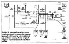
My question is rather about how this explanation relates to the schematic. For convenience I reproduce it here (from the diyaudio store):

Looking at the positive output side, my assumptions are that:
1. the R6/R7 voltage divider is connected to the output voltage through R16 (in series); and
2. the LM329's output (at around 6.9V) is provided to the non-inverting input of the AD825 through R4 (in series).
If these assumptions are correct, how are the statements that
and
also correct?
AFAIK the inputs are somewhat lower than 6.9V because the LM329's output drops a bit over R4, and the voltage divider that determines the output voltage includes R16, not just R6 and R7. Is it just that the effects of R4 and R16 are small and may be neglected for practical purposes or am I misunderstanding the circuit?
And, unrelated but out of curiosity: what is the purpose of R16?
Your help is much appreciated.
Also, I hereby pre-emptively include the usual disclaimers about being a relative noob and not trained in EE and would appreciate to be educated gently...
The document that is available in the diyaudio store on the subject of customising the output voltage says this:
The most important insight is that in normal operation, the two inputs to the opamp are pretty much equal in voltage. As the stock unit uses a 6.9V LM329 reference diode (D5), connected to the non-inverting input, immediately you know those opamp inputs need both to be at 6.9V.
The output voltage is divided down by R14 and R13 for the inverting input. So if you want 10V output, R14 and R13 need to be selected so that this 10V is divided down to 6.9V at the inverting input. So there must be 6.9V across R14 and (10-6.9=3.1) across R13.
This give us a direct and simple equation: R13/R14=3.1/6.9. Assuming you select R14 first, then R13=(3.1/6.9)*R14. Like when you select R14=4.9k, then R13 needs to be (3.1/6.9)*4.9=2.2k. (You may need to play a bit with the R14 value so R13 comes out an existing value).
I understand all of this, in principle.
My question is rather about how this explanation relates to the schematic. For convenience I reproduce it here (from the diyaudio store):
Looking at the positive output side, my assumptions are that:
1. the R6/R7 voltage divider is connected to the output voltage through R16 (in series); and
2. the LM329's output (at around 6.9V) is provided to the non-inverting input of the AD825 through R4 (in series).
If these assumptions are correct, how are the statements that
The output voltage is divided down by R7 and R6 for the inverting input
and
those opamp inputs need both to be at 6.9V
also correct?
AFAIK the inputs are somewhat lower than 6.9V because the LM329's output drops a bit over R4, and the voltage divider that determines the output voltage includes R16, not just R6 and R7. Is it just that the effects of R4 and R16 are small and may be neglected for practical purposes or am I misunderstanding the circuit?
And, unrelated but out of curiosity: what is the purpose of R16?
Your help is much appreciated.

Kunlun121 -
If you are looking for explanations on how and why everything works in the SuperReg, you would really have to follow all the links in Post #1 and then some of the links that Jan has provided in his Linear Audio articles, which you can get to from the Post #1 links.
Not trying to be short with you, just kind of hard for someone to post all that info here in a single response to your post.
If you want to save time and get started building, and then enjoying listening to music with a SR, just ask what Output Voltage you want out of your SR, and I am sure you will get plenty of responses to help you out. Then in your spare time - you can go through all those links and learn how and why everything works ( if you really want to )
Just trying to be helpful 🙂
Hi dvd7900. Point taken. Articles read. Answers found.
(My question about the voltage at the inputs arose from having lost track of some basics of opamp operating principle. I get that now.)
The other point about the voltage divider I apparently got right. I asked because for ease of calculation I wanted to reproduce in Excel this table at the diy audio store page:

Which worked out nicely once I took the 100R at the +VDC sense line into account:

So far so good. (The five bottom rows are values that appear in Ken Ozard's table. I included them to make sure my sheet behaves the same way Ken's does.)
To follow your suggestion: I need two SRs, one with +30V and one with +20V output. My calculation shows 3k25 (30V unit) and 1k8 (20V unit) for R6, assuming 1k for R7 and LM329 as reference on both boards. Is that correct? I may play around with these if necessary to arrive at E96 or E24 values but they look pretty good.
Here are some more questions about the project. (I plan to use the AD825 as per the recommendation that comes with Jan Didden's boards.)

(My question about the voltage at the inputs arose from having lost track of some basics of opamp operating principle. I get that now.)
The other point about the voltage divider I apparently got right. I asked because for ease of calculation I wanted to reproduce in Excel this table at the diy audio store page:
Which worked out nicely once I took the 100R at the +VDC sense line into account:
So far so good. (The five bottom rows are values that appear in Ken Ozard's table. I included them to make sure my sheet behaves the same way Ken's does.)
To follow your suggestion: I need two SRs, one with +30V and one with +20V output. My calculation shows 3k25 (30V unit) and 1k8 (20V unit) for R6, assuming 1k for R7 and LM329 as reference on both boards. Is that correct? I may play around with these if necessary to arrive at E96 or E24 values but they look pretty good.
Here are some more questions about the project. (I plan to use the AD825 as per the recommendation that comes with Jan Didden's boards.)
- Does the value affect the performance in any way? (Assuming the ratio is correct for the output voltage.) I mean: is that irrelevant or is there any difference to be expected from higher rather than lower values (or vice versa)?
- Furthermore, from the materials available in the diyaudio store, I get that the zener's value must be increased to around half the output voltage. This would make 15V and 10V respectively for my 30V and 20V output SRs. Correct?
- Any other changes I should incorporate in my schematic for these output voltages? (Relative to the schematic in the diyaudio store.)
- One thing I wonder is why Ken's table includes a section with higher reference voltages for the SRs with a higher output. Is that necessary or preferable or can I stick with an LM329 at around 6.9V for both my output voltages? If a higher reference is needed, what part is recommended?
- There appear to be different versions of the LM329. The Sjöström units that I have previously built came with the LM329DZ variant. In one of Walt Jung's articles I read that DZ was the "loose tolerance version". Don't know why that would be preferable. Mouser has AZ, BZ, and CZ (A being more expensive (and lower stock) than B and C versions). What's the difference between these? The LT datasheet is totally un-informative on the difference:
- What about capacitor recommendations? I assume that Jan's 1995 Panasonic HFQ recommendation is obsolete now. Recent posts in this thread recommend Nichicon UKZ electrolytic for their low leakage current. Someone else suggested UKL for their apparently lower leakage current spec. (I have not checked these specs.) Is there a consensus among members about the most suitable cap? Or will any ole electrolytic do? (If so, I'll stick to Panasonic FR, which I have previously used in power supplies.)
- How about for C12? One of Jan Didden much older posts about the SR (different thread, same forum), he wrote:
Correct. I think I actually made the point in the article. I recommended NOT to use very high quality foil caps at the supply output (those .1 or 1 uF ones everybody seems to insist on) as they promote instability.
In fact, with those low output iompedances, the ONLY purpose of the output caps is to stabilise the supply. Since they are in fact in parallel with the Zout of, as Scott says, 0.000001 Ohms, it is difficult to imagine the output cap to have any role in supplying power at all.
(That Zout value is for the AD797.) Does this comment apply to C12 (which is so much smaller value than the 100nF Jan mentioned) or is it less of an issue with the AD825 as it is apparently more stable? Is a decent film cap (KT, KP, or styroflex) useful here? Or should that really be ceramic only as per the BOM in the diyaudio store?
KUNLUN121 -
30 VOLT OUTPUT ( Assuming 6.9 VREF )
R7 / R14 = 665 ohm
R6 / R13 = 2.1 K
D2 / D7 = 15V Zener ( 1N5245 or eqv. )
20 VOLT OUTPUT ( Assuming 6.9 VREF )
R7 / R14 = 768 ohm
R^ / R13 = 1.33 K
D2 / D7 = 10 V Zener ( 1N5240 or eqv. )
I would doubt there is any measurable or audible difference between using a LM329 D or A grade
in the regulator circuit, but if your just building 1 or 2 regs, I would spring a couple of bucks more
for the A grade.
Main reason being that there appear to be measurable differences with a different higher quality reference
according to some of the research at WALT JUNG.ORG and there is definitely audible differences with these upgraded reference circuits
according to some folks in this forum. This is however a whole other topic and does require other changes to the reg circuit.
For C11 / C12 use NPO/COG 100pf.
For the Electrolytics, your Panasonic FR’s will be OK except for the Output caps ( C4 C8 )
The FR’s are Low ESR caps and may cause the reg to oscillate.
Just use any General Purpose cap from one of the big name companies for C4 and C8 and you should be fine
Looking for advise:
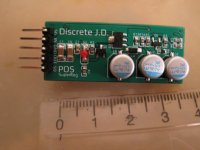
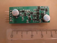
Build:
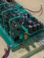
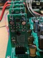
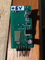
I build a +5V Jung-Didden super regulator. As I have not much space, I needed to design a new PCB using SMD components.
Differences with the original are the BJT's, I've used 2SA1163BL(CCS) + 2SD1733 (series bjt), these are quite some faster as the original's used. Opamp is a AD817.
The "big" output cap is not installed on the small regulator boards, instead, I've installed a small tantalum 4µ7 cap.
I've used the sense lines and installed the 10R + 10n, as decribed in the article (REGULATORS FOR HIGH-PERFORMANCE AUDIO).
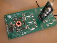
The sense lines are running on the bottom PCB (picture 1) up to the header to insert the DAC IC, this IC has local decoupling 100n COG next to pin's).
I use this to power the +5V for a TDA1541A DAC.
Problem:
On the scope when probing between the GND and the output of the regulator, I don't notice any difference. This looks good to me.
However sometimes the regulator goes in oscillation, I was able to simulate this when touching the sense connection on the regulator PCB.
Installing a series R of about 1 R between regulator output and 100µf output cap (Nichion Fine Gold), this solves the issue it seems.
Question:
Any Idea what could be the root cause? The -5V and -15V regulator's don't have this issue.
Is installing a small series R between regulator output and output cap, a good idea?
Other, better options to solve the problem?
Thanks
Build:
I build a +5V Jung-Didden super regulator. As I have not much space, I needed to design a new PCB using SMD components.
Differences with the original are the BJT's, I've used 2SA1163BL(CCS) + 2SD1733 (series bjt), these are quite some faster as the original's used. Opamp is a AD817.
The "big" output cap is not installed on the small regulator boards, instead, I've installed a small tantalum 4µ7 cap.
I've used the sense lines and installed the 10R + 10n, as decribed in the article (REGULATORS FOR HIGH-PERFORMANCE AUDIO).
The sense lines are running on the bottom PCB (picture 1) up to the header to insert the DAC IC, this IC has local decoupling 100n COG next to pin's).
I use this to power the +5V for a TDA1541A DAC.
Problem:
On the scope when probing between the GND and the output of the regulator, I don't notice any difference. This looks good to me.
However sometimes the regulator goes in oscillation, I was able to simulate this when touching the sense connection on the regulator PCB.
Installing a series R of about 1 R between regulator output and 100µf output cap (Nichion Fine Gold), this solves the issue it seems.
Question:
Any Idea what could be the root cause? The -5V and -15V regulator's don't have this issue.
Is installing a small series R between regulator output and output cap, a good idea?
Other, better options to solve the problem?
Thanks
Attachments
The low esr input/output caps is not good for J.D. regulator, you should notice that in Tina simulator in bode plot. In my case 90 mili ohm (15mohm cap + 68 mohm resistor in series with cap) produce good bode plot. Or try with an higher esr caps e.g. one with 100 miliohm esr.
Hi Savan,
For output cap, I'm fully aware of this, but even wihth 1 Ohm in series with output cap, I have oscillation.
This J.D. is supplied by +8V delivered from a LM317 with only a 10µf tantalum cap (nothing else). On the J.D. board is a 100µF pana FR.
Something strange is goiing on in combination with the TDA1541A, but what??
Remember as I mentioned in post 3236, all other regulators have identical setup, and no issues.
- Home
- The diyAudio Store
- Super Regulator