There is another important thing besides noise, and that is the (dynamic) impedance. LM329,TL431 and similar has a lower impedance than the zener diode.
Thank you for your insight! Could you please elaborate on why 1V below 7V? For example, what would be wrong with using a 2.5V reference for the 5V output with OPA1641? (I assume that by "reference" you mean D5/D10 in Jan's circuit. Please correct me if I am wrong.) Thanks again!The OPA1641 can be used for voltages lower than 7V, but only with a 1V reference.
Not at this time. I am trying to rebuild my LNA and it's kicking my butt. Also the AD825 and OPA848 are SMD, I do not want to take them off and reattach them again. I will look, I may have a couple noise measurements with just 6.9V zeners. I am at work right now, it will be later tonight.Rick, would it be possible for you to measure the noise of the two SRs you showed, with AD825 and OPA848, replacing D2 and D5 with 7.5v zeners and see what's the produced noise compared to LM329?
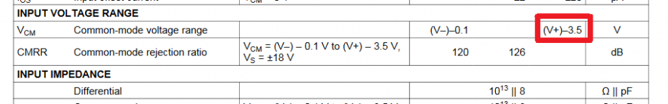
The problem with the jfet op amp at low voltages is the input voltage range, more precisely the common mode voltage range. Bipolar op amps do not have these problems at low voltages.Thank you for your insight! Could you please elaborate on why 1V below 7V? For example, what would be wrong with using a 2.5V reference for the 5V output with OPA1641? (I assume that by "reference" you mean D5/D10 in Jan's circuit. Please correct me if I am wrong.) Thanks again!
Attachments
I think you're wasting your time, I don't know if you've read this ; GLED431 and 2New_VrefsNot at this time. I am trying to rebuild my LNA and it's kicking my butt. Also the AD825 and OPA848 are SMD, I do not want to take them off and reattach them again. I will look, I may have a couple noise measurements with just 6.9V zeners. I am at work right now, it will be later tonight.
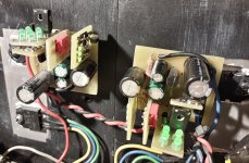
Look at my regulators for +/-19V 3A, there is no LM329 and zener anywhere, only green LEDs
Attachments
Yes, I get it now. Thank you for stopping me from making a costly mistake. I appreciate it!The problem with the jfet op amp at low voltages is the input voltage range, more precisely the common mode voltage range.
Agreed. I'm not sure you would be able to pick which was being used on a piece of equipment being used. I can say the ZTX951 is a VERY low noise piece. I would go with one of the examples above if starting from scratch.I think you're wasting your time, I don't know if you've read this ; GLED431 and 2New_Vrefs
Look at my regulators for +/-19V 3A, there is no LM329 and zener anywhere, only green LEDs
One last question on OPA1641, if I may. Are there any performance or noise issues with any of these two circuits: a voltage divider after the reference and the reference section flipped? (Only relevant parts are shown.) Thanks again for your help!The OPA1641 can be used for voltages lower than 7V, but only with a 1V reference.
Attachments
I have used LEDs many times in amplifiers as CCS. So I would be willing to try them on the SR. Would like to listen to Jan's opinion on this.
Do you have to select them for voltage drop? Or just use them for "usual" drop voltage? Greens are supposed to be 2.1v, and there are other drops according to color.
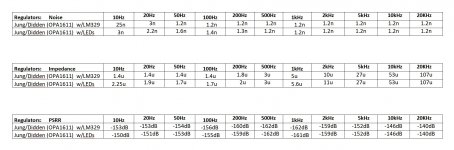
Before waiting for these answers I went ahead and simmed the SR with LEDs replacing D2 and D5. These were the results I got, and these are the ASC files.
Please tell me if I did something wrong or if the results are "legit".
Do you have to select them for voltage drop? Or just use them for "usual" drop voltage? Greens are supposed to be 2.1v, and there are other drops according to color.
Before waiting for these answers I went ahead and simmed the SR with LEDs replacing D2 and D5. These were the results I got, and these are the ASC files.
Please tell me if I did something wrong or if the results are "legit".
Attachments
As blue and white seem to have a 3.6v drop each, I tried 2 blue ones on each LED group, but I got 8v output, not 15v. Why?
Are there blue leds with different voltage drop?
I must explain that I am insisting on other reference options because the LM329 is not available where I live.
Are there blue leds with different voltage drop?
I must explain that I am insisting on other reference options because the LM329 is not available where I live.
Hello everyone,
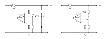
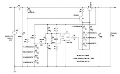
I have a somewhat conceptual question. On the attached highly simplified diagram, the regulator on the left is the original Jan Didden's circuit with no changes whatsoever (other than 2 batteries shown). A lot of parts are not shown only to simplify the question. Please imagine they are all still in place. The part numbers are the same as in Jan's circuit.
The regulator on the right is mostly the same, except the positive and negative channels have been flipped. The positive channel is moved from the top to the bottom and produces a negative output voltage. Similarly, the negative channel is moved from the bottom to the top and produces a positive output voltage. Obviously, the original circuit ground is no longer the ground, etc.
The second change is in the power supply of both opamps as shown. This apparently removes the need for the zenners and their filtering capacitors, because the opamps are already properly biased within approximately 0.7V. (The 10-Ohm resistors R3 and R10 between the output of the opamps and the base of the power transistors are still in place, just not shown to simplify the comparison). All changes from the original circuit are highlighted in red.
My question is if the modified circuit would work and if so, does it have any disadvantages compared to the original circuit specifically while using batteries. I realize that batteries are no longer connected to the ground, but I don't see why this would matter for the functionality.
Are there any concerns with noise or anything else? Or is this totally wrong and it would explode with fireworks? I would appreciate any insight. Thank you!
If I redraw the +ve regulator in a form I'm more familiar with, if I'm not mistaken it should behave similarly for both a +ve and -ve output voltage:
I have seen a similar scheme using an integrated regulator (which fundamentally comprises an error amplifier and emitter follower), for example from hifisonix (consider the bridge rectifier output to be the 'battery'):
Thanks for confirming the first part of my question. What about feeding each opamp with the output voltage of both regulators and removing the zeners?
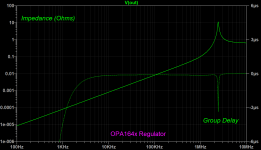
Just a couple notes -- when measuring the output impedance you can put both DC value on the current (25mA seems to be acceptable) and AC=1. You don't need the load resistor.Please tell me if I did something wrong or if the results are "legit".
As the load increases, the output impedance will decrease BUT you fool yourself into thinking that the regulator is stable. Steve Sandler wrote a paper on the topic:
https://www.omicron-lab.com/fileadm...ce/AppNote_OutputImpedance_Stability_V1.0.pdf
When measuring PSRR, omit the input capacitor. This, as the resistance of the injection source into the regulator input will affect results.
It's called "Non-Invasive Stability Measurement", NISM. Coined by Steve Sandler, not me!
Right click on the left vertical axis and convert from dB to logarithmic. Right click on the right vertical axis and change from "phase" to "group delay" (tg). The "Q" of the circuit is given by:
Q = π * f * tg.
Knowing Q, you can use the Ericson Maksimovic approximation to calculate phase margin (within a few degrees):
Phase Margin =~ 50.36 × Q^-0.907
- Home
- The diyAudio Store
- Super Regulator