Noise is the least of the problems.
Well then, among the AD825, AD797, and LT1028 would one be preferred when the PS is intended to feed a TXCO?
I'm using the AD797 in the I/V for the ES9018, it stroke me with a kind of oddity to use the same chip in the SSR01 and SSR02. Instead I opt for the LT1028, so far so good, perfect sound to me. The SSRs do give out exact the same voltage ... 12.26 Volt to the last digit accurate ... pos and neg ... cool ...
At 0 dB gain the AD825 has a very good phase characteristics compared to the AD797 and LT1028.
I guess it's fortunate that's what I used for my two SSR01s! 🙂
How about selling the board through the Diy store ?
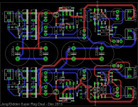
Any though of selling the board through the diy store ?I finally bit the bullet and layed out a set of superreg boards based on the original 1995 series articles, updated after Walt's 4/2000 article.
These are the successor boards to the ones Jack showed here.
All info is here: The Superregs
Let me know if there's anything I missed or got wrong.
jan
Any though of selling the board through the diy store ?
Yes, if they want it. I offered it to Mark (Variac).
Now we wait for their response . Thanks .Yes, if they want it. I offered it to Mark (Variac).
Should link to this thread as it about the same thinghttp://www.diyaudio.com/forums/ever...-linear-audio-publication-68.html#post3522061
Yes, if they want it. I offered it to Mark (Variac).
Well, if it helps to get a vote - here it is! 🙂
make it two !Well, if it helps to get a vote - here it is! 🙂
For your interest :
http://www.diyaudio.com/forums/ever...-linear-audio-publication-14.html#post3522371
Patrick
http://www.diyaudio.com/forums/ever...-linear-audio-publication-14.html#post3522371
Patrick
HEre is my attempt at a dual rail version using SMD. Jackinnj has made some suggestions in another thread I will attempt to implement.
I chose LT1792 based on a recommendation by EUVL and because it will allow for the possibility of larger output voltages, if needed. The caps are Panasonic FM, spec'ing slightly better than recommended replacements of FC. Of course FC can be used as I believe they are equivalent in size. I may have oversized the caps just for freedom in choice. The board is 2.5" x 3". I will work on the revision and appreciate any comments. This will be used for a DCB1 to start and then for a phono pre. It will be compared to the Salas Shunt in both cases. The phono pre is the aplication that will need larger output voltages.
moderator should probably move your post to the "Super Regulator collecting the facts" thread -- an observation -- the sense resistors shouldn't be at right angles, the error amplifier should be rotated 90 degrees so that pins 2 and 3 have the shortest possible route to the sense resistors. using capacitors larger than those specified by Walt will affect the performance of the regulator. those originally specified in the 1995 article are no longer available so use panasonic fc.
I chose LT1792 based on a recommendation by EUVL and because it will allow for the possibility of larger output voltages, if needed. The caps are Panasonic FM, spec'ing slightly better than recommended replacements of FC. Of course FC can be used as I believe they are equivalent in size. I may have oversized the caps just for freedom in choice. The board is 2.5" x 3". I will work on the revision and appreciate any comments. This will be used for a DCB1 to start and then for a phono pre. It will be compared to the Salas Shunt in both cases. The phono pre is the aplication that will need larger output voltages.
Attachments
Last edited:
I'm checking interest for a group buy for my dual voltage super regulator power supply. See my sig below for links.
Hello
I am designing an active filter for my speakers. I have access to a circuit board milling machine that can do 2 sides. I plan to make one 100x160 mm board. I will supply it with unregulated, single 24V DC.
I plan to have space, on the corner of the board, for one super regulator. My question is, which instructions should I follow in laying it out? The latest design by Walt Jung? Some update to it? Of all the articles I have skimmed through, is the one from year 2000 the latest?
I am purely an engineer. I don't believe in "tuning" it for "sound" or changing things and listening for effects. But were there any unsolved concerns with stability or startup that I should know? Which parts list should I follow? I plan to use regular parts, i.e. not to surface mount anything.
Also. I will maybe regulate the 24V down to 18V and create an artificial earth at 9V. Should I use the 24V supply as a floating +/-12V instead and have two regulated rails? Or will I be fine with creating an artificial earth after the regulator?
I don't know how well your two sides will register once you flip over the PCB.
How about drilling two registration holes in diagonally opposite corners to help with accurate setting up of the second side?
How about drilling two registration holes in diagonally opposite corners to help with accurate setting up of the second side?
Hello
I am designing an active filter for my speakers. I have access to a circuit board milling machine that can do 2 sides. I plan to make one 100x160 mm board. I will supply it with unregulated, single 24V DC.
I plan to have space, on the corner of the board, for one super regulator. My question is, which instructions should I follow in laying it out? The latest design by Walt Jung? Some update to it? Of all the articles I have skimmed through, is the one from year 2000 the latest?
I am purely an engineer. I don't believe in "tuning" it for "sound" or changing things and listening for effects. But were there any unsolved concerns with stability or startup that I should know? Which parts list should I follow? I plan to use regular parts, i.e. not to surface mount anything.
Also. I will maybe regulate the 24V down to 18V and create an artificial earth at 9V. Should I use the 24V supply as a floating +/-12V instead and have two regulated rails? Or will I be fine with creating an artificial earth after the regulator?
The Jung/Didden reg PCB is now available through the diyaudio store. I updated the 1995 design to Walts' 2000 design.
See http://www.diyaudio.com/forums/diyaudio-store/247281-super-regulator-6.html for example.
Jan
Last edited:
Another layout
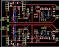
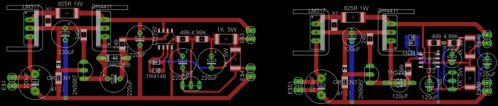
I have been using an earlier variant of the "Jung super reg" for years with satisfaction. I decide to make a small batch of PCB of the revised version. I choose LT1363 as the comparator because I subjectively like its sound.
See if you have any comments on this layout. I am a newbie in PCB layout. There maybe many mistakes.
Attachments
- Home
- Amplifiers
- Power Supplies
- Super Regulator, collecting the facts