You removed the C suffix from some but not all of Bob C's models?
btw: in the case of the BC550C and 560C, the C is meant to be the gain suffix ranking and not cordell's.
I'll tell you what I do, back before Bob C's models, more often than not when I used
Onsemi or Fairchild models there would be at least one if not more completely defective
model in nearly every simulation that I did. Fairchild was only slightly better. I have no
faith at all in any models from Onsemi or Fairchild. Things got a bit better when andy_c's
output models came out, and a lot better with Bob C's.
One hint in simulation is that when it takes a long time to run, there is often a model
problem and I'm seeing this in your simulation.
I just subbed in ALL Bob C models except for the outputs and it seems to be much better.
But I'm just getting started.
The way I'm doing the models is to include Bob C's file unmodified, changing to types that
are in his library with a C suffix, and I made a model.txt with all the varieties of 2N3055s.
If I don't find some good 2N3055 models I'm just going to use MJ21193/4 and then you
can fine tune it in real hardware.
What vintage are your 2N3055's? not from the 1960s-70s I hope which would be single
diffused types. Those have something like an 800 KHz Ft.
Last edited:
I looked over the output stage carefully and something jumps out at me as not right. The
driver transistors turn on the outputs and most often there is a resistor from base to emitter
to turn them off.
Typically 100 ohm resistors are used on output devices but a lower value turns them off
faster. The easiest way to see what should be there is to look at the Heathkit schematic
for R141 and R143 - Leach's student got it right but they are a bit low.
Another clever thing that he did was to keep the emitters on the series connected output
independent allowing him to eliminate the .22 ohm emitter resistors - nice.
The driver for the series outputs is also missing a base to emitter resistor in Leach's amp.
This would be R147 in the Heathkit amp.
Something strange in the Heathkit is R137 being 22 ohms that really biases the drivers, hot
very hot. We usually see 50 to 100 ohms there but if you can provide enough heat sink,
and you have much lower rails so it would probably work even with 22 ohms. Big devices
need high bias to get to a more optimal operating point. Also R137 turns off the main
outputs, the lower the value the faster the turn off.
You asked about the fuses in the Heathkit - those are to protect the VAS and front end,
they are only 60mA. You mentioned that the Leach protection clamp doesn't work, did
you use devices with good performance at low Vce?
Last edited:
Here's a schematic with resistors added, values can be adjusted as needed, arrows in
red point out the 4 additional resistors.
If it looks like I compressed your schematic, I did, since I do my relaxed work on a
laptop and I couldn't read things very well without the changes.
red point out the 4 additional resistors.
If it looks like I compressed your schematic, I did, since I do my relaxed work on a
laptop and I couldn't read things very well without the changes.
Attachments

Last edited:
All notes on the Heathkit:
Note the use of 15 ohm base stoppers on the drivers in the Heath, R134 and R136, and the
low value for R133.
Note that the predriver collector goes to the rail rather than the half way point. If I had to
guess I'd say that they used the MJE340/350 for the predriver and VAS.
The HF compensation around the series output devices, their drivers and pre-drivers is there
to adjust the gain of the EF to keep it roughly unity even up to 50 KHz or more. And also to
tame any tendency for local oscillation.
Last edited:
This resistance would be 10 ohm only 1watt
?????? This resistance? Which resistor?
The picture is just for discussion, I'll keep simulating without the resistors and try to come
up with a test case showing how they do not turn off fast enough.
up with a test case showing how they do not turn off fast enough.
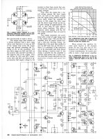
Here is the Tigersaurus schematic, it is CFP, but you can see that all the power transistors
have 100 ohms from BE. The series transistors are just an EF2 so much lower divider resistors
are required.
Note how similar the front end is to the Bryston 3B, and the output to the Tiger .01.
have 100 ohms from BE. The series transistors are just an EF2 so much lower divider resistors
are required.
Note how similar the front end is to the Bryston 3B, and the output to the Tiger .01.
Attachments
Another note, if you made the series zeners for the first cascode 15V and 25V with the 15 toward
the ground end, you could tap off +/- 15V to power an OP amp DC servo in case you have any
interest in them.
the ground end, you could tap off +/- 15V to power an OP amp DC servo in case you have any
interest in them.
I used Onsemi or Fairchild models there would be at least one if not more completely defective model in nearly every simulation that I did. Fairchild was only slightly better. I have no faith at all in any models from Onsemi or Fairchild.
It's true that those models often pose problems. I just can't understand how onsemi didn't even double check what modpex did, to make sure they did the right thing. They say those modpex models reflect the datasheets, but that's not what I found. Very unfortunate and frustrating. Why do they even bother publishing those, if they aren't good enough?
One hint in simulation is that when it takes a long time to run, there is often a model problem and I'm seeing this in your simulation.
I see this often, and when it does get super slow, there are signs of tiny very high frequency oscillations. Most of the time those oscillations are so tiny that we can't even see they on plots, and it takes a very close zoom to see the hints of them.
I just subbed in ALL Bob C models except for the outputs and it seems to be much better.
Almost all of those models in that sim were bob's, except the 3055s of course, since he doesn't have such models in his library.
The way I'm doing the models is to include Bob C's file unmodified, changing to types that are in his library with a C suffix, and I made a model.txt with all the varieties of 2N3055s.
Ok, but I prefer using the ako doodad to point to the models when I need to swap them out to test different ones, and there is less confusion as to what parts are really meant in the schematic if the part's names are the real ones.
For example as I mentioned, when I use a BC550C, the C doesn't mean it's bob's model, even if it really is, it does mean it's the suffix C for gain selection.
I have used the BC547B and BC546B for example from ltspice's library, and swapped using the ako doohickey.
If I don't find some good 2N3055 models I'm just going to use MJ21193/4 and then you can fine tune it in real hardware.
That's what I ended up doing lately, since none of the 3055 models I have would work in that sim. Although several of those models have worked just fine in other sims. I have been tweaking a few of them, starting with the VAF, and also BF. I looked at the CJC, but it was within specs, so left that alone. However I'm quite sure many other parms must be wrong, and I suspect many are missing and should be there. For example one 3055 model posted some time ago by jan didden had very few parms, so that really can't be a very representative model.
What vintage are your 2N3055's? not from the 1960s-70s I hope which would be single diffused types. Those have something like an 800 KHz Ft.
Actually there may be a few from the late 60s, but most of my old stock for those kinds of parts are from the 70s, and some early 80s. So they are definitely from that era and not the newer faster better made ones.
I may even have a couple of BDX18 somewhere, which at the time were almost the only available true complementary.
I have a fairly comparable number of the MJ2955s, but those must be mostly from the early 80s, not newer.
Plus I have a nice bunch of the 2N3442, from the same era, which are rather close to the 3055, higher Vce0 but lower current. Other than that, they're mostly similar. And I even have their BDX20 complements too.
I have an even bigger batch of the 2N3773, probably in the order of 60 of them.
Those were heavily used for some time in quasi amps from BGW. I never got any complementary types to the 3773 though.
I do have a few 2N3771 as well, but those would be better used for things like power supply regulation ballasts.
I had a limited number of 2N5631 and 2N6031 to make a big beefy amp back then in the late 70s early 80s, but unfortunately the topo I chose at the time to make an amp was opamp based, and that flopped big time. With serious oscillations I could not stop, which ended up frying all outputs. That was a dreadful fate and very frustrating, when I knew much less than now.
Typically 100 ohm resistors are used on output devices but a lower value turns them off faster.
So you mean those are missing from leach's design then.
The easiest way to see what should be there is to look at the Heathkit schematic for R141 and R143
Yes, I see those. Missing from leach's schematic. Maybe with properly tweaked models and a few such corrections, we can get to something working properly.
Another clever thing that he did was to keep the emitters on the series connected output independent allowing him to eliminate the .22 ohm emitter resistors - nice.
Right, I see this too. Then we should do this on this design, cut out those links between the stacks and drop a bunch more unnecessary parts.
Lower part count is good, and at the same time it simplifies a layout. Plus removing some overhead is good, to reduce a bit more losses.
The driver for the series outputs is also missing a base to emitter resistor in Leach's amp. This would be R147 in the Heathkit amp.
I see. Is this basically what they mean in the datasheet for things like the VceR where they mention that RBE=100ohms?
Something strange in the Heathkit is R137 being 22 ohms that really biases the drivers, hot very hot.
Right. Seems rather low, for a high bias. Maybe overkill. This is the R36 of 220ohms in the leach schematic right? But the big difference also is that in the superamp, those are stacked, and they're not in the heathkit, so that's even worse.
Maybe there is no need to go that far, we can probably reduce that bias some.
I had added a cap there on R36, hoping to speed up the turn offs.
I arbitrarily chose 2.2u for that cap, but this likely requires tweaking, or removal...
I'd be curious to know how to get this value right.
We usually see 50 to 100 ohms there but if you can provide enough heat sink, and you have much lower rails so it would probably work even with 22 ohms.
To allow using the 3055s from the early era, I purposely limited the rails to 60V, although with the various losses from emitter res plus the Vcesat and psu sagging, those rails could be 65V and still not endanger those devices really.
But once properly designed, the rails can be increased some, to allow for devices that can handle the voltage, and if the rails are raised more significantly, there may be a few parts to recalculate, such as the zener ballasts in the front end...
If someone wanted to make use of those 3055 clones, the MJ15015/6, then rails could go way up, with their Vce0 at 120V, double the original 3055s...
But then depending on the amp's usage, soa could become an issue even though the MJs are 180W instead of 115, so it might be good to consider the option of 4 sets instead of 3 for the outputs.
I simulated the 4 sets version, still using cordell's 21193/4 in the 3055's places, to make it work, and that worked better than the 3 sets version, more stable, less distortion, especially when getting close to max power.
You mentioned that the Leach protection clamp doesn't work, did
you use devices with good performance at low Vce?
I'm not saying it doesn't work. What I found is that on hard conditions, they act but not willfully enough to have enough foldback to keep in the soa. They do what they're meant to do, but not enough. (see example of soa violation posted earlier)
And I used many different parts there, including trying out schottky diodes for D7/D8 to try to minimize the left over voltage that's pinching the bias spreader, hoping to get a stronger action to get a deeper foldback.
I ended up going back to the MPSA06/56, with their lower Vcesat, which combined with the lower forward drop in the schottkys, did give a little more foldback, but still insufficient to stay in the soa.
Here's a schematic with resistors added, values can be adjusted as needed, arrows in red point out the 4 additional resistors.
But you didn't split up the stacks and remove the extra sets of .22 res.
I see you use 51ohms there, but shouldn't that relate somewhat to the value of R36?
If it looks like I compressed your schematic, I did, since I do my relaxed work on a laptop and I couldn't read things very well without the changes.
No biggie, still readable.
I've seen a lot more sims out there a lot messier and difficult to read.
All notes on the Heathkit:
Note the use of 15 ohm base stoppers on the drivers in the Heath, R134 and R136, and the low value for R133.
Ok, and no base stoppers on the predrivers...
I did add base stoppers on the predrivers in the sim where I test the protections, on the 4 sets one. That also did help the protection in return, to provide a bit more foldback, because I placed the protection's tap on the predrivers' bases and not the vas side. So the protection acts even more strongly to bring the soa violation down somewhat. Still not enough though.
And that R133 is just one, not split up like in leach's versions, for tapping an inner feedback loop.
Note that the predriver collector goes to the rail rather than the half way point.
But that's just because those predrivers aren't stacked.
If I had to guess I'd say that they used the MJE340/350 for the predriver and VAS.
Well, I've used those models in other sims and never got good results, so I stayed away from using them. The 2SA1381/2SC3503 should work fine there. We can put everything, including those, on the same main sink by the way.
The HF compensation around the series output devices, their drivers and pre-drivers is there to adjust the gain of the EF to keep it roughly unity even up to 50 KHz or more. And also to tame any tendency for local oscillation.
That's the role of that inner feedback loop tapped between the split res R34/35 right?
The picture is just for discussion, I'll keep simulating without the resistors and try to come up with a test case showing how they do not turn off fast enough.
That's going to be very interesting, and educational. 🙂
Here is the Tigersaurus schematic, it is CFP, but you can see that all the power transistors have 100 ohms from BE. The series transistors are just an EF2 so much lower divider resistors are required.
This is an interesting design. I had a couple of sims for a simpler version without stacked outputs and a single ended front end.
Would you have the whole article please? I only had that page plus the one with the pcbs on it, not the whole article.
Very simple protection. And with those beefy outputs, plenty of spare soa for the protections to act progressively and yet above legit signal.
Old devices, and yet, still manufactured by onsemi.
Besides their higher voltage, current and power handling, they're somewhat similar to the 3055s, perhaps a bit more gain, and a little faster.
A superamp version could be made with those too, and probably the 3055 based version could get those devices with hardly any changes.
Note how similar the front end is to the Bryston 3B, and the output to the Tiger .01.
Simple resistive loading, but those do have current sources, not the brystons.
Interesting stuff. That output stage with the turned around devices with their emitters towards the rails...
Another note, if you made the series zeners for the first cascode 15V and 25V with the 15 toward the ground end, you could tap off +/- 15V to power an OP amp DC servo in case you have any interest in them.
And I was just thinking one other possible use of this for opamps is for a limiter.
I've been thinking about limiters for quite some time and so far I would favor those that use a vactrol to "squeeze" the amp's input.
This makes for a very simple circuitry, easy to understand, and a single opamp can be used to sense the clipping, and then a few more parts to activate a vactrol on the amp's input, keeping the amp from clipping with a compression that only acts when clipping occurs, leaving things as is below that.
And more things could be done to act on the compression, such as thermal sensing and short circuit detection...
A Baker clamp usually goes from C to B but it might be similar just to stop deep saturation
of the outputs.
I think that you ought to try to figure out what type of 2N3055s and 2N3773s you have are
they made by RCA? One advantage of the single diffused type is that they don't have SOA
issues IIRC. Maybe a quasicomp with the 2N3773s, they are high voltage and would not
need the series connection?
I'm not sure if any of the other big guys, MOT etc., made single diffused types.
Are you aware that back in the 60s to 80s it was well known not to test an amp at 10 KHz
or above at full power or with square waves due to cross conduction failure? I wondered
how much better the newer devices are and read on here that someone ran an automated
test, probably at high/full power, that swept frequency. The MJ21193/4 blew when it got
to 200 KHz. I would stop at 20-50 KHz with newer devices.
MJ802 and 4502 look like big powerful parts but note that the constant power slope goes
to SOA limited at 50V. They are 50W parts at 50V whereas the 2n3773 for example takes
3A at 50V for 150W, MJ21193/4 are even better.
I believe that this was one of the failure modes for the smaller Tiger amps, at high power
levels with clipping, cross conduction happens, more heat then melt down.
I scratch built the Tigersaurus as a kid and it was the only Tiger that never failed, not once.
Have you seen my Tiger and Bryston simulations that show excessive reverse Vbe on the
driver transistors? If built as a Tiger .01 or Bryston style output stage a simple diode fix
seems to work in simulation.
- Home
- Amplifiers
- Solid State
- Super Leach amp simulation woes