Hi, As far as I remember in leach/super leach amp driver and pre driver operating in class A mode...
if they are adequately cooled, why we(or diodes ) should measure the temperature?
if they are adequately cooled, why we(or diodes ) should measure the temperature?
I'm surprised that you are so quick to dismiss the manufactured Leachs;
Actually I'm really not. I think it's a fine design, but I am very puzzled as to why such a widely built amp by so many people, earning good reputation, obviously because it does work, does not perform well at all in simulations. Why is that? What's wrong? models? something else? That's what I'd like to find out.
I've been working for quite some time on a leach amp build, for which I have a dedicated thread, and I was rather close to the goal with that design, with everything to build it, and not just the pcb, everything else, including the case. It's still an ongoing project of mine now.
You seem to have a high opinion of these designs, are you aware of Bob C.'s "Another View of TIM"? And the war that started over the validity of TIM? Andy_c took Leach's audio
Yes, I've read this, many times, and like the other things like that, I do re-read them once in a while (to compensate for my failing memory).
Certainly there has been more insight gained into TIM since Leach did his design, and many amps now built are low tim but aren't necessarily using quite all of the concepts put forth before, by Leach, Otala and others in the early days.
Your sim is missing the 1N4004 model, no big deal obviously.
Actually it's not. That model is in the models file but remmed out, because I have that model in my main library and it doesn't need to be enabled in the file.
Take a peek and turn it back on. I think that model is likely the one from Cordell.
Was there a particularly good case that demonstrates the instability?
Well at first I was trying to simply get the original superamp to work, with all of the values as provided by Leach. That would not work at all, with the models that came with the low tim sim, and others.
Then I tried making the 3055 version, but could not stabilize it either.
Only once using the models I mentioned, which were not the ones that the version was aiming for (3055s), was it running about ok.
And at no time did it give any really good performance, which is really why I'm quite puzzled.
Obviously the goal is to compensate the Vbe tempco so that the idle bias remains constant.
That would be very nice if this could be achieved 100% in reality, but even somewhat close can be good enough.
Count the number of junctions on devices that get hot from one VAS out to the other.
Would that basically be all the junctions the bias spreader must control?
Obviously not counting all those in parallel, those would count as one.
There are 6 in the Leach and so it seems that he is not compensating for the pre-driver.
You're referring to the original low tim. And that amp's output stage is pretty much an ordinary 3EF, so that would be 6 junctions for the bias spreader to control, regardless of how many outputs may be paralleled.
Seems that 2 of those sense diodes should go on the drivers, and two on the outputs, but most just put them on the outputs probably on the idea that they heat up the most and if the drivers begin to run away then the outputs will heat more also.
That's a good point.
Most of the time the drivers are on the same sink along with the outputs nowadays, as opposed to the early days when only a couple of TO3s were fitted by themselves on sinks and thus the leach amp was built back then with 2 such sinks and the drivers would not be sharing those.
Vbe multipliers use the gain of the transistor, obviously, to multiply one diode drop to however many junctions need to be compensated. The "diode" can be the Vbe of the transistor itself.
I figured that much. I'm seeking deeper insight into this. I've been simulating this stuff, and I need to do much more.
Gaining a better understanding of this can then be applied to other situations.
In any case, I'd be looking at using transistors, preferably in a TO126 case or similar, for easy mounting on sinks, instead of using diodes.
The mounting of a case with a screw on a sink is more reliable and repeatable, with pretty much known results, as opposed to those rigs with diodes.
And although Jens used a better trick using smt diodes in his excellent pcb design, I would never look at using any smt stuff myself, that's just not good for older folks. I couldn't ever tackle those tiny things.
I found Leach’s original arrangement of three 1N400* Si diodes forming an H best, but with the leads themselves clamped to the heatsink via a Kapton insulator. This gave a much faster response to changing temperature than the diode bodies would.
A pity your VI limiter component values aren’t shown in your sim.
What value of Vbe for the trigger transistor does your sim derive? This has a profound effect on the calculation of the device values.
Brian.
A pity your VI limiter component values aren’t shown in your sim.
What value of Vbe for the trigger transistor does your sim derive? This has a profound effect on the calculation of the device values.
Brian.
Attachments
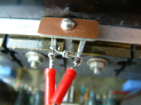
I found Leach’s original arrangement of three 1N400* Si diodes forming an H best,
His design calls for 4 diodes. Did you change that in one of your builds?
I see in your photo it's a rather tricky thing to set up. Exactly the kind of thing I wouldn't want to play around with.
but with the leads themselves clamped to the heatsink via a Kapton insulator. This gave a much faster response to changing temperature than the diode bodies would.
It likely would, but likely as well not to be as fast as what you get with a TO126 bolted on the sink.
And I have been contemplating lately the option of slapping that sensor right on the TO3, bolted with one of its screws, sharing the same screw.
Even with an insulator between the TO126 and the TO3, it's only one extra thermal junction instead of 2 if they're independently mounted on the sink, and the distance and material between the junctions would be as little as we can possibly get. This I suspect would likely be the fastest response possible.
The only small hitch would be to have to file off a tiny bit of the TO3 case to allow the TO126 to rest flat on it, depending on how that TO3 was made...
A pity your VI limiter component values aren’t shown in your sim.
What value of Vbe for the trigger transistor does your sim derive? This has a profound effect on the calculation of the device values.
Well the focus went to make it work, and the protections not being in the way is a plus.
But I did get those protections working and calculated on an other such sim, but since it wouldn't work with the 3055s, that was done using the MJ21193/4, which are a bit different, enough to change how the limiters would work.
And here again, although I noticed that depending on which transistors are used for protection, the Vbe "knee" is mostly located around 680mV or so.
I've tried quite a few possible parts for the protections, BC550C/60C, BC547B/57B, BC546B/56B, 2N5551/5401, and ended up right back to the MPSA06/56, mostly because of their lower Vcesat.
I was struggling to make the limiters work as calculated, and they never do.
They act, as planned, but not as hard as they're supposed to, so on a dead short, they are insufficient to keep it soa safe, not even close.
They are always much too progressive to act, the knee is way too soft. Those trannies are all conducting something way before the wanted threshold at their knee, so not only they intrude on the legit signal, they start lowering level way before their designed point of action.
That is why I tried things to try to make them behave somewhat more as they're supposed to. The first thing I thought was that their Vcesat was too high, so they couldn't saturate more to act more strongly to make the fold back.
So I tried various parts to compared them, and those with the lowest Vcesat are best to use for this, but still not sufficient.
So I looked for other means to allow the "pinching" effect on the spreader to be stronger, to fold back more aggressively, and so I looked into using shottky diodes instead of the regular small signals ones.
I settled on the 1N5819 because they're in LTspice's library, but I also did try a few others, such as the BAV21, which isn't even a shottky, and it didn't do any better, since their forward drop is about the same as the 1N4148.
Using the lower vcesat trannies, with the lower forward drop diodes does help better control this, but still not 100%, so in any case, whatever the calculated or set threshold is for the limiters, they start acting way way way too early, not strongly enough to prevent soa violations, and on a dead short, it's almost like it's not even there, the soa is totally violated.
If someone can show me a circuit that actually works properly as expected and as calculated, I really want to see this and try it.
But so far, to me, those statements saying that it's possible to make such limiters "transparent", and prevent any soa violations, are just like any advertisements, they're not quite true. Prove me wrong please!
Like I said earlier, the only way I can see to prevent soa violations and keep the limiters truly transparent is to provide for far more available soa than necessary, to give more than plenty of headroom to the limiters to start acting way above the legit signal and yet prevent soa violations despite their overly weak action just because the output stage is very much overbuilt.
This is what I see done for example in the McIntosh amps, where they have far more output pairs than really needed. I tried that, and those do work, just because it's totally overbuilt.
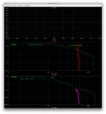
Here is to show my point about the limiters.
The posted plots are showing a definite soa violation, despite the limiters acting.
This is done on the original leach amp, as is, with his calculated published values, the outputs are the MJ15003/4, the drivers MJE15030/31 (models from the sim posted on his site), the pre-drivers are the 2N3439/5416 and the protection ones are the MPS8099/599.
That sim ran at 1khz, and I threw a dead short that would likely never be encountered in reality, at 1mohm. But a short of something like 100mohms gives about the same results.
The drivers are ok, no violations, even with the derated soa.
However although for normal use even under 2 ohms, the MJs outputs are fine, the protections don't work enough to keep them soa safe, at least in the sim.
What are we supposed to make of this? Why would a real build work better than a sim?
In my new 3055based superamp sim, I am using a more "involved" limiter, as described by Kiwanuka, with a dual slope and I have tweaked certain things, such as the caps on the bases and the sensor res, as well as the res on the bases (2k2), to make a more optimized time constant that is shorter than it really should, so the action would come in early enough, although not too late either.
This is still not enough to keep the 3 sets of outputs in their soa, and it does work much better on a 4 sets build, with minimal violation, but still some.
The thing is, if the amp is to be bridged, on an 8ohms complex load, we need to look at a legit signal under 2ohms on each amp for full power, and although this does fit quite well in the soa, the protections aren't acting properly enough to prevent violations, and while starting to act much too early on legit signal.
Attachments
Did you notice in the .pdf writeup that I linked there was mention of how the output zobel
must go on the output binding posts or else oscillation is possible? Normally, it goes before
the output inductor, so that is just one hint.
must go on the output binding posts or else oscillation is possible? Normally, it goes before
the output inductor, so that is just one hint.
Did you notice in the .pdf writeup that I linked there was mention of how the output zobel
must go on the output binding posts or else oscillation is possible? Normally, it goes before
the output inductor, so that is just one hint.
Yes, I remember reading this stuff.
But the inductor and zobel should not be needed to keep it stable on a simple resistive only load in simulation. The amp should be stable without them.
When loading the amp with something more complex and reactive, then they become much more necessary. Simulations don't even bring in RF ingress or parasitic stuff like RLC brought in by cabling and other things, unless it's explicitly added. All those extra things beyond a simple resistive load make it much more necessary to have those L//R and zobels, but the amp sim should be able to run stable without them.
The amplifier's output Zobel is there to provide a load at high frequency to control the way the amplifier behaves when no load is connected.
The amplifier's output Zobel is there to provide a load at high frequency to control the way the amplifier behaves when no load is connected.
Yes, and the amp sim with a resistive load shouldn't even need that there to be stable.
And same thing for the L//R, it's there to block ingress of RF plus help stabilize on a capacitive load, so there again, the amp sim with a resistive load and no added stuff to fake the RF ingress or a highly reactive load or any extra stuff like wiring parasitic LRC shouldn't need those things to be stable.
If an amp needs those things added in a sim to remain stable, there is something wrong with the amp.
First you ask why it oscillates in simulation, then when I point out that in some cases it
oscillated in real hardware you say it shouldn't. Hearing a lot about how it should be.
oscillated in real hardware you say it shouldn't. Hearing a lot about how it should be.
First you ask why it oscillates in simulation, then when I point out that in some cases it oscillated in real hardware you say it shouldn't. Hearing a lot about how it should be.
I'm just very puzzled about why a circuit that is proven to work just fine in reality, wouldn't work better in simulations.
If a sim works and then the real thing has issues, that's understandable, but the opposite? That really is puzzling.
Since the sims are always more ideal, with parts of the same type not having differences, no influence from RF, EMI, layout issues, cabling or whatever parasitic influences, the sims should always be more optimistic and some issues are bound to show up in a real build.
Unless the various parasitics and whatever influences are actually explicitly added in the sims, there should be nothing to think about when it comes to external perturbations that can come in and screw things up.
Now since the output L//R and zobel networks are there to deal with things coming from the outside and they are not really fulfilling that role in the sims, they have a minor influence on the sims, and a stable amp without those should still be stable. Shouldn't it? Am I wrong about this somewhere?
If an amp needs the belts and braces in sim to keep it together, then something must be wrong with stability for sure.
you have still got it mixed up.
The Thiele Network comes in two parts.
The R+C from out to audio ground helps to stabilise the amplifier by providing a high frequency load
The L||R helps to isolate load reactance to maintain the stability margins that allow the amplifier to work in the presense of a reactive load.
The Thiele Network comes in two parts.
The R+C from out to audio ground helps to stabilise the amplifier by providing a high frequency load
The L||R helps to isolate load reactance to maintain the stability margins that allow the amplifier to work in the presense of a reactive load.
you have still got it mixed up.
The Thiele Network comes in two parts.
I haven't got that mixed up. That's what I was saying earlier. Although I bundled them together when I said "networks", I know what each of them do.
The R+C from out to audio ground helps to stabilise the amplifier by providing a high frequency load
The L||R helps to isolate load reactance to maintain the stability margins that allow the amplifier to work in the presense of a reactive load.
Exactly what I was saying earlier. And the point was that in a sim, which doesn't bring in the various outside world perturbations, unless explicitly included in the sim, those output networks don't do much, except influence a little some things like margins, but not enormously.
And since we run sims most of the time with resistive loads, then those output networks don't have much to do.
So here again, I would think a stable amp on a pure resistive load shouldn't need those output networks to remain stable, and if not stable without those networks, then that amp has stability issues to begin with.
The leach amp, including the superamp, have ample margins, even without those output networks. More than sufficient to keep it stable, and yet, there are issues showing up in sims, but nothing much in real builds. Why is that?
I'm just very puzzled about why a circuit that is proven to work just fine in reality, wouldn't work better in simulations.
If a sim works and then the real thing has issues, that's understandable, but the opposite? That really is puzzling.
Since the sims are always more ideal, with parts of the same type not having differences, no influence from RF, EMI, layout issues, cabling or whatever parasitic influences, the sims should always be more optimistic and some issues are bound to show up in a real build.
Unless the various parasitics and whatever influences are actually explicitly added in the sims, there should be nothing to think about when it comes to external perturbations that can come in and screw things up.
Now since the output L//R and zobel networks are there to deal with things coming from the outside and they are not really fulfilling that role in the sims, they have a minor influence on the sims, and a stable amp without those should still be stable. Shouldn't it? Am I wrong about this somewhere?
If an amp needs the belts and braces in sim to keep it together, then something must be wrong with stability for sure.
I'm not sure what to say here, are you aware that a single small signal stage EF can
oscillate as a Colpitts oscillator due to device parasitic capacitance and lead inductance?
Many people here are finding that active small signal current sources and beta enhanced
VAS's can oscillate without some treatment. This is sensitive to the devices used and
some work around it by using device types that are known to work. There were recent
posts in Bob C's book thread about this - in the last 3 months or so.
I've already mentioned that base lead wiring inductance in the real world can help stop
HF local oscillations in the same way as base resistor stoppers work. Harman Kardon
used them (LR networks) in their old amps.
It's complicated and you'd have to build and compare to simulations to determine what is
causing the differences when there is no obvious issue.
One guideline is that if the oscillations are roughly 500K to 2 MHz it is probably the global
loop. If above 2 MHz then probably local to the devices. If above 50 MHz it is probably
local to a small signal device.
One more thing, the zobel's main purpose is to load the output stage at HF when there is
no output load. Actually even if you put a resistive load on the output it is decoupled by
the output inductor, so the zobel is needed to provide that load.
Wish there was a more conclusive answer/solution.
Last edited:
I'm just starting to look at the details of your simulation. I see the zobel moved to the
correct location.
correct location.
I'm not sure what to say here, are you aware that a single small signal stage EF can
oscillate as a Colpitts oscillator due to device parasitic capacitance and lead inductance?
Many people here are finding that active small signal current sources and beta enhanced
VAS's can oscillate without some treatment. This is sensitive to the devices used and
some work around it by using device types that are known to work. There were recent
posts in Bob C's book thread about this - in the last 3 months or so.
That's more a concern in real builds and not really in simulations.
But of course when a circuit simulates fine, it's no guarantee that it will work quite the same for real. But that's where prototyping comes in...
I've already mentioned that base lead wiring inductance in the real world can help stop HF local oscillations in the same way as base resistor stoppers work. Harman Kardon used them (LR networks) in their old amps.
This is something to keep in mind when making something real.
Wish there was a more conclusive answer/solution.
That's ok, we just need to make something work right first in sim, then a prototype is in order. The thing is, prototyping is only good to do if there is a minimum of test equipment to troubleshoot and measure. Otherwise it's a shot in the dark pretty much.
I'm just starting to look at the details of your simulation. I see the zobel moved to the correct location.
Yes.
One thing that would come out a plus by removing some of the stuff, it's the reduced complexity and part count. And at the same time it might just get more stable as well as easier and cheaper to make.
You removed the C suffix from some but not all of Bob C's models?
Yes. The models were not always from cordell at first, so they didn't have that suffix and I was swapping them around using the :ako to point to whatever I wanted.
The models from cordell are identified in the model itself in the mfg argument.
When I first started that sim, it was done with the models from leach's site.
- Home
- Amplifiers
- Solid State
- Super Leach amp simulation woes